
- The Harsh Reality of Automotive Environments
- Material Selection and Design Features for Harsh Environments
- Design Guidelines for Balanced Flexibility and Rigidity
- Thermal Management and Material Expansion Considerations
- Rigorous Reliability Testing and Verification
- Practical Recommendations for Engineers and Manufacturers
Rigid-flex PCBs represent a significant advancement in circuit board technology, combining rigid board sections with flexible regions into a single integrated structure. This hybrid design enables advanced routing solutions and compact packaging that traditional rigid boards simply cannot achieve. In automotive electronics, where space constraints meet extreme environmental demands, rigid-flex PCBs have become increasingly essential. However, the unique combination of materials and mechanical properties introduces challenges that demand rigorous testing before these circuits hit the road. Heat and vibration aren’t just theoretical concerns—they’re daily realities that can turn a seemingly robust design into a field failure within months of deployment.
The Harsh Reality of Automotive Environments
Automotive electronics operate in some of the most demanding conditions any PCB will face. Temperature fluctuations represent a constant challenge, with underhood components experiencing swings from -40°C during winter storage to 125°C or higher near engine compartments during operation. Understanding vibration resistant PCB design principles becomes critical when these thermal extremes compound mechanical stresses. These temperature cycles don’t occur gradually—rapid transitions happen during engine startup and shutdown, creating thermal shock conditions that stress every material interface within the PCB assembly.
Continuous vibration adds another layer of complexity. Road surfaces transmit mechanical energy throughout the vehicle, creating vibration frequencies typically ranging from 10 Hz to 2,000 Hz. Studies indicate that vibration-induced failures account for nearly 20% of PCB issues in automotive systems, with particularly high rates in advanced driver assistance systems (ADAS) operating at higher frequencies. When you combine thermal cycling with vibration, the failure mechanisms compound exponentially—thermal expansion and contraction weaken solder joints while simultaneous vibration accelerates their deterioration.
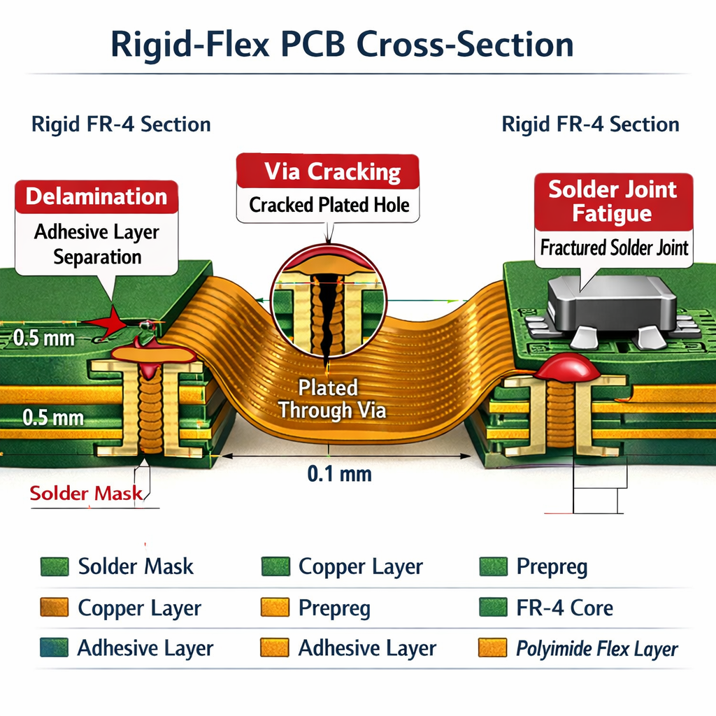
The mechanical stresses manifest in specific failure modes. Delamination occurs when adhesive layers between rigid and flexible sections separate due to coefficient of thermal expansion (CTE) mismatches combined with flexural stress. Via cracking develops when plated through-holes experience differential expansion between copper plating and substrate materials under thermal cycling. Solder joint fatigue, perhaps the most common failure mode, results from repeated thermal expansion coupled with vibration-induced shear forces. A solder joint that might endure 10,000 thermal cycles in static conditions may fail after just 3,000 cycles when exposed to simultaneous vibration.
Unlike consumer electronics that operate in climate-controlled environments, automotive applications face exposure to moisture, chemicals, electromagnetic interference, and mechanical shock—all while maintaining signal integrity and electrical performance. This reality demands materials and design innovations specifically engineered to survive automotive conditions.
Material Selection and Design Features for Harsh Environments
The foundation of reliable rigid-flex PCBs in automotive applications begins with appropriate material selection. Engineers must balance thermal stability, mechanical flexibility, and cost-effectiveness when choosing between polyimide substrates and emerging alternatives like TPU flexible PCB materials for specific design requirements. Polyimide-based substrates serve as the industry standard for flexible regions due to their exceptional thermal stability, maintaining mechanical properties across the full automotive temperature range. Unlike cheaper polyester alternatives that soften above 105°C, polyimide materials remain dimensionally stable up to 250°C, providing the thermal margin necessary for underhood applications.
Low-CTE adhesives play an equally critical role at material interfaces. Traditional acrylic adhesives exhibit coefficients of thermal expansion around 50-70 ppm/°C, creating significant stress at rigid-to-flex transitions where CTE mismatches concentrate. Modern adhesiveless constructions or specialized low-CTE adhesive systems reduce this mismatch to under 30 ppm/°C, dramatically reducing interface stress during thermal cycling. The adhesive selection also impacts mechanical fatigue resistance—modern formulations maintain bond strength through thousands of flex cycles while resisting delamination under combined thermal and vibration stress.
Strategic stiffener placement represents a crucial design feature for managing mechanical stress. Stiffeners serve dual purposes: they provide mechanical support for component mounting areas while controlling stress distribution at flex-to-rigid transitions. Properly designed stiffeners gradually transition stress from rigid sections into flexible regions, preventing stress concentration points that accelerate failure. Material selection for stiffeners matters too—FR-4 stiffeners work well for general applications, while stainless steel or polyimide stiffeners offer better CTE matching for extreme environments.
Optimized copper trace layouts reduce both mechanical and thermal stresses throughout the circuit. Curved traces rather than sharp right-angle turns distribute mechanical stress more evenly during flexing. Copper weight selection balances current-carrying capacity against mechanical flexibility—heavier copper (2 oz) provides better current handling but reduces flex life compared to lighter copper (0.5 oz). For high-power applications requiring sophisticated thermal strategies, review high power flex PCB heat dissipation design approaches that complement mechanical durability. Trace routing parallel to bend axes rather than perpendicular minimizes strain on conductors during flexing, extending fatigue life significantly.
The layer stackup itself serves as a design feature for stress management. Symmetric constructions with balanced copper distribution prevent warping during thermal cycling. Placing copper layers equidistant from the neutral axis during bending equalizes strain across all conductive layers, preventing preferential fatigue in outer layers. Modern designs often incorporate hatched copper planes rather than solid fills in flex regions, reducing stiffness while maintaining electrical performance.
Design Guidelines for Balanced Flexibility and Rigidity
Achieving the right balance between flexibility and rigidity requires careful attention to geometric parameters. Bend radius represents the most critical mechanical specification—maintaining generous bend radii prevents excessive strain in copper traces and substrate materials. The industry standard minimum bend radius equals ten times the total PCB thickness for dynamic flexing applications (flex regions that bend repeatedly during operation) and six times thickness for static flexing (one-time installation bending). Automotive applications typically demand conservative margins, often using 12-15 times thickness for dynamic flex regions to ensure adequate fatigue life.
Smooth transitions between flex and rigid sections require proper stiffener design and placement. Abrupt transitions create stress concentration points where failures initiate. These design flaws represent one of the most common flex PCB failures that experienced engineers have learned to prevent through proper stiffener geometry. Best practice involves extending stiffeners at least 3mm beyond the rigid section boundary, then tapering their edges to create gradual stiffness transitions. The taper angle should remain below 30 degrees to prevent excessive stress gradients. Some designers incorporate intermediate stiffener zones with varying thickness to create multi-stage transitions, further distributing stress over greater distances.
Layer stackup planning demands careful attention to CTE alignment across layers. When combining rigid FR-4 sections (CTE around 14-17 ppm/°C in-plane) with polyimide flex regions (CTE around 12-16 ppm/°C), the goal is minimizing differential expansion during thermal cycling. Symmetric stackups with balanced copper distribution help—placing equivalent copper weights on outer layers prevents preferential expansion that causes warping. Some designs incorporate low-CTE rigid materials like ceramic-filled epoxies in critical sections to better match polyimide characteristics.
Impedance control and signal integrity considerations become more complex in rigid-flex designs. The dielectric constant varies between rigid sections (FR-4 typically around 4.2-4.5) and flex regions (polyimide typically 3.2-3.5), requiring trace width adjustments to maintain consistent impedance. High-speed signals demand particular attention—routing critical signals through flex regions requires controlled impedance design accounting for the thinner dielectrics and different material properties. Ground plane continuity across transitions prevents impedance discontinuities that cause signal reflections.
Component placement relative to flex regions requires strategic planning. Heavy components should mount on rigid sections, preferably centered over support areas to minimize dynamic loading on flex regions during vibration. When components must mount near flex-to-rigid transitions, stiffeners should extend beneath component footprints to prevent stress concentration on solder joints. Connector placement deserves special attention—mounting connectors on rigid sections near flex transitions subjects the flex region to mechanical stress during mating cycles, potentially initiating fatigue failures.
Thermal Management and Material Expansion Considerations
Thermal management in automotive rigid-flex PCBs extends beyond simple heat dissipation—it encompasses managing the thermal expansion behavior of diverse materials throughout the assembly. CTE mismatch represents the fundamental challenge. When a rigid FR-4 section bonds to a polyimide flex region, their different expansion rates create interfacial stress during every thermal cycle. At 100°C temperature rise, a 100mm FR-4 section expands approximately 0.14-0.17mm, while an equivalent polyimide section expands 0.12-0.16mm. This seemingly small difference creates significant shear stress at bonding interfaces, particularly when repeated thousands of times during normal vehicle operation.
Minimizing CTE mismatch begins with material selection. Specifying low-CTE FR-4 materials (CTE values closer to 13-14 ppm/°C) for rigid sections reduces the differential with standard polyimide. Some applications benefit from high-performance polyimides with CTE values as low as 3 ppm/°C for critical flex regions, though these materials carry cost premiums. The key is matching materials to the application’s thermal cycling severity and reliability requirements.
Avoiding high-stress adhesive joints requires careful attention to bonding layer design. Adhesiveless constructions eliminate one source of CTE mismatch entirely, though they demand precise manufacturing controls. When adhesives are necessary, selecting formulations with intermediate CTE values (around 40-50 ppm/°C) and high elongation capabilities (>50% elongation at break) allows the bondline to accommodate expansion differences through elastic deformation rather than creating interfacial stress.
Designing for expected temperature ranges demands understanding the specific application environment. Underhood automotive electronics typically face -40°C to +125°C operational ranges, with potential excursions to +150°C near exhaust systems. Interior applications operate from -40°C to +85°C. Each 10°C increase in maximum operating temperature reduces MTBF (mean time between failures) by approximately 50% for temperature-sensitive failure mechanisms. Conservative design practices include derating component temperature ratings by at least 20°C below maximum expected operating temperatures and designing thermal paths that maintain junction temperatures well below absolute maximum ratings.
Thermal pathway design in rigid-flex assemblies requires strategic planning. Unlike rigid PCBs where heat spreads relatively uniformly across copper planes, rigid-flex designs must account for thermal resistance at material transitions. Flex regions generally exhibit higher thermal resistance than equivalent rigid sections due to thinner copper weights and polyimide’s lower thermal conductivity compared to FR-4. Critical thermal design involves routing heat-generating components to rigid sections with adequate copper plane areas, then designing thermal vias to conduct heat into internal copper layers where it distributes more effectively.
Rigorous Reliability Testing and Verification
Comprehensive reliability testing provides the only genuine assurance that rigid-flex PCBs will survive automotive environments. The IPC-9701 standard establishes rigorous test protocols specifically designed to evaluate solder joint performance under combined thermal and mechanical stress conditions representative of automotive operation. IPC-9701 testing standards specifically address the performance requirements for rigid-flex boards under mechanical and thermal stress conditions relevant to automotive applications. These standards define test methods for flex endurance, thermal cycling, vibration resistance, and combined environmental stressing that simulates actual field conditions.
Accelerated thermal cycling represents a fundamental reliability test, exposing assemblies to rapid temperature transitions between extreme hot and cold conditions. Typical automotive qualification involves 500-1000 cycles between -40°C and +125°C with 15-minute dwell times at each extreme and transition rates of approximately 10°C per minute. The rapid transitions create maximum thermal shock stress, revealing weaknesses in solder joints, vias, and material interfaces. Inspection intervals occur at 100, 250, 500, and 1000 cycles, with destructive analysis of failed samples to identify failure mechanisms and root causes.
Vibration testing subjects assemblies to sinusoidal or random vibration profiles matching automotive environments. Sinusoidal vibration sweeps from 10 Hz to 2,000 Hz at specified acceleration levels (typically 5-20 G depending on mounting location), while random vibration applies broadband energy across the frequency spectrum. Testing occurs in all three axes with durations from 4-24 hours per axis. Modern automotive standards often require combined temperature-vibration testing, where assemblies undergo vibration stress while exposed to elevated temperatures (typically +85°C to +125°C), creating worst-case combined loading conditions.
Humidity and thermal humidity assessments evaluate assembly resistance to moisture-induced degradation. Temperature-humidity-bias (THB) testing applies 85°C/85% relative humidity conditions while powering the circuit, accelerating moisture-induced failures like electrochemical migration and corrosion. Durations typically range from 500-1000 hours for automotive qualification. These tests particularly stress flex-to-rigid transitions where moisture can penetrate if bonding is inadequate, causing delamination and electrical failures.
Flexural endurance testing specifically evaluates flex region performance through repeated bending cycles. Test fixtures subject flex regions to controlled radius bending (typically matching the design minimum radius) through thousands or millions of cycles, depending on whether the application involves dynamic or static flexing. Dynamic flex applications require demonstrating adequate performance through at least 100,000 flex cycles, often extending to 1,000,000 cycles for high-reliability automotive applications. Understanding these flexible circuit reliability issues early prevents discovering failure modes only after production deployment. Electrical monitoring during flex testing detects intermittent failures or resistance increases indicating impending conductor fracture.
Combined stress testing provides the most realistic assessment of field reliability. Exposing assemblies simultaneously to elevated temperature, vibration, and electrical bias replicates actual operating conditions far better than sequential single-stress tests. Industry data shows that failure rates under combined stress conditions often exceed predictions based on individual stress testing by factors of 2-5X, highlighting the importance of realistic qualification testing.
Practical Recommendations for Engineers and Manufacturers
Early collaboration between design engineers and manufacturing partners represents the single most effective strategy for preventing field failures. Engaging flexible PCB manufacturers during the concept phase—before finalizing circuit designs—enables design-for-manufacturing optimization that addresses potential reliability issues before they’re embedded in the design. Manufacturing partners bring specialized knowledge about material limitations, process capabilities, and failure modes that design engineers may not encounter in rigid board design. This collaboration should include formal Design Failure Mode Effects Analysis (DFMEA) reviews examining potential failure mechanisms and their root causes at every material interface and mechanical transition.
Prototyping cycles serve as essential learning opportunities that shouldn’t be rushed or eliminated. The first prototype iteration reveals how theoretical designs perform in physical form—how flex regions actually bend, where stress concentrates at transitions, and whether assembly processes work as intended. Comprehensive testing of initial prototypes, including at least abbreviated thermal cycling and vibration exposure, identifies design weaknesses before committing to production tooling. Many successful programs incorporate two or three prototype iterations with increasingly rigorous testing at each stage, gradually building confidence in the design’s robustness.
Design priorities that minimize failure risks start with conservative mechanical specifications. When uncertain about appropriate bend radius, choose larger values—the marginal cost of additional PCB area costs far less than field failures. Transition regions deserve particular attention; investing engineering effort in optimized stiffener designs and gradual transitions pays dividends in long-term reliability. Material selection should prioritize proven automotive-grade materials over cost optimization in initial designs; cost reduction efforts work better after establishing a reliable baseline design.
Adhering to industry standards provides crucial design guardrails. Beyond IPC specifications, automotive electronics manufacturers must comply with automotive-specific rigid-flex PCB standards that address sector-unique environmental and safety requirements governing vehicle electronics systems. IPC-2223 sectional design standard for flexible printed boards offers detailed guidance on geometric parameters, material selection, and construction methods. IPC-6013 qualification and performance specification for flexible printed boards defines acceptance criteria and test methods ensuring consistent quality. IATF 16949 automotive quality management standard governs manufacturing processes for automotive suppliers, ensuring process controls prevent defects. Compliance with these standards provides both design guidance and quality assurance frameworks that reduce risk significantly.
Conducting comprehensive testing throughout development cycles catches problems early when they’re less expensive to fix. • Component-level testing verifies individual flex sections and rigid-flex transitions before system integration.
• Assembly-level testing validates complete circuits under realistic electrical loading.
• System-level testing examines installed assemblies in representative vehicle environments. Each testing stage builds confidence while identifying different failure modes—component testing reveals material and process issues, assembly testing uncovers design weaknesses, and system testing validates real-world performance.
The investment in proper design practices, quality materials, and rigorous testing may seem substantial during development, but it pales compared to the costs of field failures. Warranty claims, product recalls, and brand reputation damage from premature failures cost manufacturers far more than design optimization and qualification testing. Studies across automotive electronics show that every dollar invested in design validation and reliability testing saves approximately ten dollars in field failure costs. For companies building products that protect lives and enable critical vehicle functions, ensuring long-term reliability through comprehensive testing isn’t optional—it’s the foundation of responsible engineering and manufacturing excellence.