
For engineers developing products with flexible circuits, time-to-market often means the difference between capturing an opportunity and watching competitors pull ahead. Yet many design teams unknowingly embed weeks of delays into their projects before fabrication even begins. The culprit? Poor Design for Manufacturability (DFM).
DFM isn’t just a checklist item—it’s the difference between receiving functional boards in days versus cycling through costly redesigns for weeks. For professionals working on automotive electronics, medical devices, or consumer products requiring certified flexible PCB solutions, mastering DFM fundamentals transforms production timelines from unpredictable to reliably fast.
Why Quick-Turn DFM Matters More Than Ever
In sectors like aerospace and telecommunications, product development cycles compress while complexity increases. A smartphone manufacturer launching a new wearable needs prototypes yesterday. An automotive supplier integrating flexible circuits into EV battery management systems can’t afford fabrication delays when OEM deadlines loom.
Traditional PCB turnarounds of 2-4 weeks no longer cut it. Quick-turn services now deliver boards in 24-72 hours—but only when designs arrive manufacturing-ready. The harsh reality? Fabricators refuse designs with manufacturability issues or hold production for clarifications, turning promised 3-day deliveries into 2-week ordeals.
Consider a real scenario: A medical device manufacturer submitted a 4-layer rigid-flex design for a wearable glucose monitor. The design looked perfect in their CAD software, but proper material selection and trace specifications were overlooked. Three days later, instead of receiving boards, they got a fabrication hold notice. Issues included trace widths below the manufacturer’s minimums, vias too close to bend regions, and missing copper balance specifications. Resolution took five days of back-and-forth communication, plus another week for revised fabrication. A “quick-turn” project consumed three weeks—all preventable with proper DFM.

Critical Design Constraints That Control Your Timeline
Understanding manufacturing constraints separates designs that flow smoothly through production from those that trigger delays. Let’s break down the essentials.
Trace Width and Spacing: While your CAD tool might allow 0.03mm traces, quick-turn flexible circuit manufacturers typically support minimum trace widths of 0.05mm (2mil) with 0.05mm spacing as standard capabilities. Going below these thresholds requires specialized processing that eliminates “quick” from quick-turn. For rush projects, designing with 0.075-0.1mm traces (3-4mil) provides manufacturing margin that speeds production. Understanding these manufacturing process constraints early prevents costly delays.
Via Design: Vias in flexible circuits demand careful attention. Minimum via sizes typically range from 0.2-0.3mm diameter, but quick-turn services prefer 0.4mm or larger. More critically, via placement in flex regions creates reliability concerns. Position vias at least 1.5mm from bend areas to prevent stress cracking during assembly or use. For applications involving dynamic flexing—like smartphone hinges or robotic joints—push this distance to 3mm minimum.
Panelization Strategy: How you panel designs profoundly impacts turnaround. Standard panel sizes (typically up to 600x600mm) process faster than custom formats requiring special tooling. When prototyping multiple design variants, arrange them on standard panels to avoid setup time. A design engineer at an industrial controls company reduced their prototype cycle from 7 days to 3 by consolidating four flex circuit variants onto a single standard panel instead of ordering four separate custom panels.
Material Selection: Sticking with standard substrate materials—particularly polyimide (PI) in common thicknesses like 25μm, 50μm, and 75μm—enables faster processing. Exotic materials or non-standard thicknesses require special procurement that adds days. Similarly, specifying standard copper weights (18μm or 35μm) versus custom options (like 70μm) impacts timeline. For guidance on matching materials to application requirements, consider substrate properties early in design. For quick turns, match your material specs to what manufacturers stock regularly.
The balance between design ambition and manufacturability becomes most apparent in stack-up complexity. A 2-layer flexible circuit processes significantly faster than an 8-layer design. Each additional layer adds processing steps, inspection points, and potential yield risks. When schedules matter, challenge yourself to simplify layer counts without sacrificing functionality.
Building Effective Manufacturer Partnerships
The relationship between design teams and fabricators determines whether quick-turn capabilities actually deliver quick results. Treating your PCB manufacturer as a partner rather than a vendor transforms outcomes.
Early Involvement: Engage fabricators during design development, not after finalizing layouts. At FlexPlus, we’ve found that design reviews during schematic phases prevent 60% of common DFM issues. A 15-minute consultation about bend radius requirements or material recommendations saves days of redesign later. This collaborative approach aligns with quick-turn prototyping strategies that compress development cycles. Share initial concepts and ask questions like: “We’re targeting 0.06mm traces here—will that cause issues?” or “This section needs to fold 180 degrees repeatedly—what’s your recommended construction?”
Complete Data Packages: Incomplete submissions kill timelines. Your manufacturer needs more than Gerber files. Provide comprehensive documentation including:
- Gerber files for all layers (with clear layer naming)
- NC drill files with plated/non-plated specifications
- IPC-2581 or ODB++ files when available
- Fabrication drawing showing dimensions, materials, finish requirements
- Stack-up specifications detailing layer sequence and thicknesses
- Special instructions for areas requiring particular attention
A procurement specialist at a telecommunications equipment manufacturer eliminated 48 hours from their average turnaround by creating a standardized data package template. Every submission includes the same comprehensive information, reducing clarification requests to near zero.
Interpreting Feedback Diligently: When fabricators flag potential issues, treat these as valuable insights, not obstacles. DFM reports typically categorize findings by severity: critical issues preventing fabrication, warnings about yield risks, and optimization suggestions. Address critical items immediately. For warnings, discuss trade-offs with your manufacturer. Sometimes accepting slightly higher cost enables faster turnaround by avoiding design changes.
One design team working on an aerospace sensor initially dismissed a manufacturer’s warning about their chosen coverlay material. Two weeks and three prototype iterations later, delamination issues forced them back to the manufacturer’s originally recommended material. Trusting expertise the first time would have saved significant schedule and budget.
Understanding Real-World Turnaround Times
“Quick-turn” means different things depending on your design complexity. Setting realistic expectations prevents planning disasters.
Single and Double-Layer Flex: Simple single or double-sided flexible circuits with standard features typically achieve the fastest turnarounds—24 to 72 hours from approved design to shipment. These boards require fewer processing steps and present minimal yield risks. A consumer electronics company prototyping simple flex interconnects for LED lighting consistently receives boards within 48 hours by maintaining straightforward designs with generous tolerances.
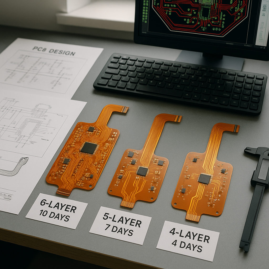
4-6 Layer Flex and Rigid-Flex: Multilayer constructions require additional lamination cycles, inspection stages, and testing. Realistic quick-turn timelines extend to 5-7 days. However, designs with excellent DFM—standard materials, appropriate tolerances, clear documentation—often land at the shorter end of this range. Those with marginal specs or unusual requirements drift toward longer timelines or exit “quick-turn” territory entirely.
Complex Rigid-Flex: Rigid-flex circuits with 8+ layers, multiple rigid sections, or specialized features like controlled impedance rarely achieve sub-week turnarounds. These designs require 7-10 days even with perfect DFM. Understanding this reality helps planning. If your rigid-flex prototype timeline is critical, invest heavily in DFM validation before submission.
The DFM Correction Factor: Here’s the uncomfortable truth: fabrication holds for DFM issues add 2-5 days to every project they affect. A 3-day quick-turn becomes an 8-day ordeal when clarifications ping-pong between teams. Proactive DFM validation before submission—even if it takes an extra day on your end—reliably saves more time than it costs.
Practical Design Tips for Maximum Speed
Armed with understanding, let’s translate knowledge into action with specific techniques that enable genuinely fast turnarounds.
Use Standard Footprints: Custom pad geometries require extra verification and potentially special tooling. Standard component footprints from your manufacturer’s library flow through production faster. When your design requires unique pad shapes, flag these early in discussions to confirm capabilities and timeline impacts.
Align with Fabricator Capabilities: Different manufacturers maintain different equipment and process capabilities. FlexPlus‘s standard minimum trace width of 0.05mm might be another manufacturer’s premium capability requiring extended processing. Before finalizing designs, obtain your chosen manufacturer’s standard capability document and design to their “standard” specs, not their “minimum” specs. You’ll pay less and receive boards faster.
Simplify Stack-Ups: Challenge every layer in your design. Can two signal layers consolidate through creative routing? Can power distribution use copper pours instead of dedicated planes? A design team developing medical wearables reduced their 6-layer flex to 4 layers through such questions, cutting prototype turnaround from 7 days to 4 while reducing costs by 30%.
Include Test Access: Design with testing in mind by including test points or probe-accessible features. This enables faster functional validation at the manufacturer and during your own bring-up. Boards that can’t be easily tested delay projects when issues arise.
Provide Adequate Documentation: Create clear, detailed fabrication drawings. Ambiguous notes like “standard finish” or “typical bend radius” force clarification delays. Specify everything explicitly: “ENIG finish, 3-5μm gold over 5μm nickel” and “Minimum bend radius: 10x material thickness.” Over-communication prevents under-delivery.
Design Conservative Bend Regions: In areas requiring flexing, provide extra margin. If calculation suggests 5mm bend radius suffices, design for 6-7mm. Use curved traces rather than sharp 90-degree angles in flex regions. Avoid placing components within 3mm of bend lines. These practices prevent stress-related failures that would otherwise surface during assembly or field use, triggering redesigns.
Avoiding Common Quick-Turn Pitfalls
Even experienced teams stumble on recurring issues that sabotage speed. Awareness enables avoidance.
Overly Tight Tolerances: Specifying tolerances tighter than functionally necessary slows production or increases costs. Does your design truly require ±0.025mm hole position tolerance, or would ±0.1mm work? The latter processes faster. A quality assurance team at an automotive supplier reviewed their typical specifications and found 40% of tolerances were unnecessarily tight—holdovers from copy-pasted templates. Relaxing these to appropriate levels improved average turnaround by one full day.
Missing or Incorrect Drill Files: Surprisingly common, incorrect drill files cause fabrication holds every time. Verify your drill file includes:
- Correct hole sizes
- Plated versus non-plated designations
- Proper units (inches versus millimeters—confusion here causes obvious problems)
- Matching hole locations to your layout
Inadequate Clearances: Minimum clearances between copper features, between copper and board edges, and around cutouts must meet manufacturing requirements. Violations here aren’t negotiable—fabricators will hold production. Design rule checking in your CAD tool catches most issues, but manually verify critical areas.
Incomplete or Contradictory Documentation: Fabrication drawings that contradict Gerber files create confusion requiring resolution before production starts. Ensure all documentation tells the same story. When making design changes, update ALL affected documents simultaneously.
Unrealistic Expectations: Finally, acknowledge that some designs simply cannot achieve quick turnaround. A 10-layer rigid-flex board with blind vias, impedance control, and multiple material types requires time for quality execution. Pushing fabricators beyond process capabilities compromises reliability. Better to plan realistic schedules than force speed that yields unusable boards.
The Engineering Partnership Advantage
Throughout this discussion, one theme emerges consistently: successful quick-turn projects depend on strong manufacturer relationships. At FlexPlus, our 20+ years specializing in flexible and rigid-flex PCBs taught us that communication quality matters as much as manufacturing capability.
Our ISO 9001, ISO 13485, IATF 16949, and ISO 14001 certifications reflect commitment to systematic quality and environmental responsibility. But certifications alone don’t accelerate your projects—the engineering partnership does. When design teams call with questions during layout, our production engineers provide real-time guidance based on actual manufacturing constraints, not theoretical minimums.
This approach aligns with our broader philosophy: advancing technology responsibly requires collaboration between innovators and manufacturers. Your breakthrough automotive sensor or medical device concept deserves manufacturing partners who view your success as their success.
For applications ranging from EV battery management systems to wearable medical devices, from aerospace avionics to telecommunications infrastructure, the path from concept to production runs through careful DFM implementation. Standard capabilities like our minimum 0.05mm trace width, multilayer flex up to 8 layers, and rigid-flex configurations up to 12 layers provide the foundation. Advanced capabilities—ultra-thin constructions down to 25 microns, specialized TPU circuits for medical wearables, or innovative thermal management solutions—extend possibilities.
Yet capability means nothing without usability. That’s why we emphasize comprehensive design support: DFM analysis identifying manufacturability issues before they become delays, material consultation matching substrate properties to your application requirements, and technical feedback throughout development.
Conclusion: Speed Through Preparation
Achieving true quick-turn flexible circuit production isn’t magic—it’s methodical DFM application combined with effective manufacturer partnership. Designs that ship in days rather than weeks share common characteristics: appropriate complexity for the timeline, specifications aligned with standard manufacturing capabilities, complete accurate documentation, and early collaborative discussion of requirements.
The next time you launch a flexible circuit project with aggressive timelines, invest time up front validating manufacturability. Engage your fabricator during design, not after completion. Challenge your specifications to eliminate unnecessary complexity. Provide comprehensive data packages eliminating ambiguity.
These practices transform quick-turn from a marketing promise into a reliable planning tool. Your products reach market faster. Your development cycles compress. Your competitive position strengthens. And manufacturing—that step often viewed as a necessary bottleneck—becomes an enabler of innovation rather than an obstacle to it.
At FlexPlus, we’re committed to being that enabler for engineers, procurement teams, and quality professionals developing the next generation of electronic products. Whether you’re integrating flexible circuits into electric vehicle systems, designing medical devices requiring ISO 13485 compliance, or developing consumer electronics demanding high-volume production, our goal remains consistent: providing certified excellence that helps your technology advance responsibly and rapidly.
The difference between shipping in days versus weeks often comes down to decisions made during initial design. Choose wisely, design thoughtfully, and partner strategically. Your timeline will thank you.