
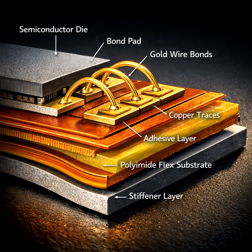
When advanced packaging meets flexible substrates, the engineering challenges multiply exponentially. Wire bonding on flex and rigid-flex PCBs represents a convergence of two mature technologies that, when combined, create a unique set of technical obstacles. Yet this combination is rapidly becoming essential across automotive electronics, medical devices, and high-performance consumer applications.
The reality? Most design teams discover these challenges far too late in their development cycle.
The Growing Importance of Wire Bonding on Flexible Substrates
Traditional rigid PCBs have dominated electronics for decades, but the industry is experiencing a fundamental shift. Flexible and rigid-flex circuits are no longer niche solutions—they’ve become mainstream requirements. In automotive applications, from battery management systems to advanced driver assistance systems (ADAS), flexible circuits enable connections that must survive extreme temperature cycling, constant vibration, and tight space constraints that rigid boards simply cannot accommodate.
Medical device manufacturers face similar pressures. Wearable health monitors, implantable devices, and surgical instruments demand circuits that bend, flex, and conform to three-dimensional spaces while maintaining signal integrity and reliability. Consumer electronics brands push the envelope further, cramming more functionality into thinner profiles where every millimeter counts.
Wire bonding has traditionally been the workhorse interconnection technology for semiconductor packaging, offering cost-effectiveness and proven reliability. Now, as these die-level connections must interface with flexible substrates, engineers confront a new reality: the flexible nature of the substrate fundamentally changes how wire bonds behave, how stress distributes during thermal cycling, and how mechanical reliability degrades over time.
At FlexPlus, we’ve witnessed this evolution firsthand over 20+ years of flexible PCB manufacturing. Our customers increasingly request complex assemblies that combine chip-on-board (COB) integration with flexible substrates—solutions that demand deep understanding of both wire bonding physics and flexible circuit behavior.
The Technical Foundation: Understanding Wire Bonding Methods
Wire bonding encompasses several distinct techniques, each with specific advantages and limitations when applied to flexible substrates. Understanding these fundamentals is critical before addressing the unique challenges of flex PCBs.
Ball bonding forms the industry standard for gold and copper wire interconnections. The process begins by melting the wire tip into a spherical ball using an electric flame-off (EFO) spark. This ball is then pressed onto the bond pad with controlled force while simultaneous heat and ultrasonic energy create a metallurgical bond. The second connection—typically on the die side—uses a crescent or “stitch” bond. Ball bonding offers excellent loop control and works well with fine-pitch applications, but requires careful thermal management that becomes more complex on flexible substrates.
Wedge bonding creates connections through ultrasonic energy and mechanical pressure alone, without requiring heat or ball formation. A wedge-shaped tool presses the wire against the pad while ultrasonic vibrations generate friction and atomic diffusion at the interface. This cold-bonding process reduces thermal stress—a significant advantage for temperature-sensitive flexible materials—but provides less flexibility in loop shaping and typically requires larger bond pad areas.
The choice of bonding wire material matters profoundly. Gold wire remains the premium choice for its excellent corrosion resistance and bondability, though copper wire has gained traction due to cost advantages and superior electrical conductivity. Aluminum wire, while less common in modern applications, still appears in specific automotive and industrial contexts.
Substrate compatibility extends beyond the base material to include surface finishes. Electroless Nickel Immersion Gold (ENIG) provides excellent bondability for both ball and wedge bonding. Immersion Silver offers good thermal performance but requires careful handling to prevent oxidation. Organic Solderability Preservative (OSP) finishes present challenges for direct wire bonding and often necessitate alternative approaches or additional processing steps.
These technical fundamentals create the foundation, but flexible substrates introduce variables that rigid PCB designers never encounter.
Why Flexible Substrates Change Everything
Flex and rigid-flex PCBs solve problems that rigid boards cannot address, but they also introduce challenges that fundamentally alter wire bonding reliability.
Higher interconnect density represents one key advantage. Flexible circuits eliminate bulky connectors and enable direct chip-to-board connections in three-dimensional spaces. A smartphone camera module exemplifies this perfectly—multiple sensors, processors, and optical components connect through a sculptured flex circuit that folds into a compact Z-height profile impossible with rigid boards and wire harnesses.
Reduced assembly complexity appears when designs eliminate intermediate connectors. Each connector represents a potential failure point, adds height to the assembly, and requires additional handling during manufacturing. Wire bonding directly to a flexible substrate reduces these connection points by up to 87%, creating more reliable signal paths with fewer opportunities for mechanical failure.
Improved electrical performance emerges from shorter signal paths and reduced parasitics. High-speed automotive radar sensors, operating at 77 GHz, benefit enormously from the reduced inductance and capacitance achievable through direct wire bonding to carefully designed flex transmission lines.
Yet these benefits come with significant challenges that must be addressed during both design and manufacturing.
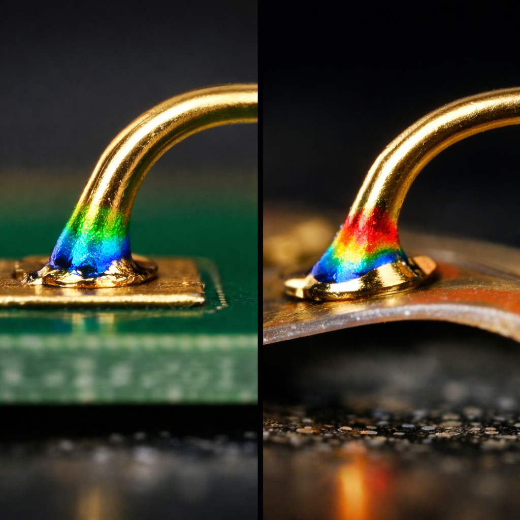
Thermal expansion mismatch creates the primary reliability concern. Silicon dies have a coefficient of thermal expansion (CTE) around 2.6 ppm/°C. Polyimide flex substrates measure approximately 12-20 ppm/°C—nearly an order of magnitude higher. During temperature cycling from -40°C to +125°C (common in automotive applications), this CTE mismatch generates substantial shear stress at the bond interface.
Consider a 5mm die bonded to a flex substrate. A 100°C temperature swing creates differential expansion of approximately 50-80 microns. This strain concentrates at the wire bond heel—the point where the wire emerges from the bond pad—potentially causing fatigue cracks that propagate through the metallurgical interface.
Flexural stress compounds the thermal challenges. Unlike rigid substrates that remain geometrically stable, flexible circuits experience bending during both assembly and end-use operation. Medical catheter assemblies, for instance, must survive thousands of flexing cycles while maintaining electrical continuity. Each flex cycle imposes additional stress on wire bonds, particularly when bending radii approach the minimum allowable limits.
The combination of thermal cycling and mechanical flexing creates a synergistic degradation mechanism more severe than either stress alone. This reality demands specialized design approaches and manufacturing processes that go far beyond traditional rigid PCB wire bonding practices.
Fabrication Complexities: From Rigid-Flex Stack-Up to Bond Pad Layout
Rigid-flex PCB manufacturing introduces fabrication complexities that directly impact wire bonding success. The construction process itself creates challenges that designers must anticipate from the earliest concept stages.
Layer stack-up design becomes exponentially more complex in rigid-flex constructions. A typical 8-layer rigid-flex board might include four rigid layers in the primary component areas, transitioning to two flexible layers in the bending regions. These transitions occur through carefully controlled adhesive zones where no-flow prepreg prevents resin migration into flex areas during lamination.
The bond pad area requires particularly careful stack-up consideration. Flex circuits naturally have less dimensional stability than rigid boards due to the inherent flexibility of polyimide. During the wire bonding process, the substrate must remain stable under the bonding tool force—typically 30-80 grams force for ball bonding, higher for wedge bonding. Insufficient support beneath bond pads causes deflection during bonding, resulting in inconsistent bond formation and reduced reliability.
FlexPlus addresses this through integrated stiffener design. We use FR-4 or stainless steel stiffeners bonded precisely beneath bond pad arrays, creating local rigid zones within the flexible circuit. The stiffener thickness, adhesive selection, and edge transition design all influence both bondability and long-term reliability.
Adhesive selection impacts multiple performance parameters simultaneously. Acrylic adhesives provide excellent flexibility and peel strength but offer lower glass transition temperatures (Tg), limiting their use in high-temperature wire bonding processes. Epoxy-based adhesives withstand higher bonding temperatures but sacrifice some flexibility. The bonding process itself can generate temperatures exceeding 150°C in the immediate bond zone, placing thermal stress on the adhesive layer.
For automotive applications requiring IATF 16949 certification, we typically recommend high-temperature epoxy systems with Tg above 180°C. Medical device applications under ISO 13485 often prioritize adhesive biocompatibility alongside thermal performance. These material choices must be locked in during early design phases—changing adhesives later requires complete requalification of the manufacturing process.
Bond pad geometry and layout directly determine wire bonding success on flexible substrates. Pad size must balance competing requirements: larger pads improve bonding process windows and mechanical reliability but consume valuable circuit area. Our experience suggests minimum pad dimensions of 100μm × 100μm for fine-pitch gold ball bonding on flex substrates, with 125μm × 125μm providing more robust process margins.
Pad-to-pad spacing presents another critical parameter. While rigid PCBs readily achieve 50μm pitch wire bonding, flexible substrates typically require 75-100μm minimum pitch to accommodate substrate movement during the bonding process and ensure adequate wire loop clearance during subsequent flexing.
The copper trace routing beneath bond pads requires attention that rigid board designers often overlook. Traces should avoid running directly under bond pads when possible, as trace presence creates localized stiffness variations that affect bond formation consistency. When traces must pass under pads, symmetric routing patterns help maintain uniform substrate compliance across the pad array.
Specialized Wire Bonding Techniques for Flexible Success
Standard wire bonding processes require significant adaptation when applied to flexible substrates. These modifications address the unique mechanical and thermal characteristics that flexible circuits introduce.
Thermal management becomes paramount. The heat applied during thermosonic ball bonding can damage adhesive layers or cause local polyimide degradation if not carefully controlled. We’ve developed proprietary bonding parameters that reduce substrate temperature exposure while maintaining bond integrity. This involves lower bonding temperatures (140-160°C vs. 200°C+ on rigid boards), shorter bonding times, and optimized ultrasonic energy profiles.
For temperature-sensitive assemblies—such as medical devices with integrated sensors or pharmaceutical delivery systems—ultrasonic wedge bonding provides an alternative. This cold-bonding process eliminates the thermal stress component entirely, though it requires careful optimization of ultrasonic parameters to achieve reliable bonds on the flexible substrate surface.
Bond force optimization addresses the substrate deflection challenge. Excessive bonding force causes the flexible substrate to deflect away from the bonding tool, preventing proper bond formation. Insufficient force fails to create adequate metal-to-metal contact for metallurgical bonding. We’ve developed force calibration protocols specific to different flex circuit constructions, accounting for substrate thickness, stiffener design, and underlying support structures.
Surface finish compatibility determines bonding success before the wire ever touches the pad. ENIG finish provides the most reliable results for wire bonding on flex circuits, with the nickel barrier preventing copper diffusion and the gold surface offering excellent bondability. The nickel layer must be precisely controlled—too thin risks gold-to-copper diffusion during bonding, too thick creates excessive intermetallic formation that weakens the bond.
Immersion silver presents an economical alternative but demands stringent process control. Silver oxidizes rapidly in ambient conditions, and even thin oxide layers dramatically reduce bondability. Parts must proceed directly from surface finishing to wire bonding without extended storage, or require pre-bond plasma cleaning to remove oxides.
Underbond protection strategies extend long-term reliability. The underside of wire bonds—where the wire heel meets the pad—concentrates mechanical stress during flexing and thermal cycling. We apply specialized underfill materials that encapsulate the wire heel region, redistributing stress and preventing crack initiation. These materials must be carefully formulated to maintain flexibility while providing mechanical reinforcement.
Advanced assemblies may incorporate dam-and-fill underfill processes, where a dam surrounds the die perimeter and liquid underfill material flows beneath the wire bonds through capillary action. This technique provides superior protection but requires precise dam placement and material selection to prevent interference with the flexible circuit’s designed bending characteristics.
Materials and Interlayer Strategies for Dissimilar Substrate Bonding
Bonding dissimilar materials—silicon dies to polyimide flex circuits, rigid FR-4 sections to flexible polyimide layers—creates interfaces where failure mechanisms concentrate. Understanding and controlling these interfaces determines product reliability.
Adhesive selection for die attachment directly impacts wire bonding reliability. Die attach adhesives must provide strong mechanical bonds, efficiently conduct heat from the die to the substrate, match thermal expansion characteristics as closely as possible, and withstand subsequent wire bonding process temperatures without degradation.
Epoxy-based die attach adhesives dominate due to their excellent adhesion to both silicon and polyimide, along with good thermal conductivity when filled with silver particles. For high-power applications requiring superior heat dissipation, we employ thermally conductive adhesives achieving >3 W/m·K thermal conductivity.
The die attach adhesive’s elastic modulus significantly influences wire bond reliability. Softer adhesives (modulus <5 GPa) provide stress relief during thermal cycling but may allow excessive die movement during wire bonding. Harder adhesives (modulus >10 GPa) improve bonding process stability but transmit more thermal stress to wire bonds. Our engineering team works with customers to select adhesive properties optimized for specific application requirements and expected operating environments.
Peel resistance concerns arise at rigid-flex transition zones where wire bonds may approach the flexible region. The peel strength at polyimide-adhesive-copper interfaces must exceed the mechanical forces transmitted through wire loops during flexing events. We specify minimum peel strengths of 1.0 N/mm for applications involving repeated flex cycles, verified through 90-degree peel testing.
Thermal cycling durability tests reveal potential failure mechanisms before field deployment. We conduct accelerated thermal cycling from -40°C to +125°C, monitoring wire bond resistance and performing pull testing at regular intervals. Automotive applications typically require 1,000+ cycles without degradation—a demanding target when CTE mismatches are in play.
Design considerations for bend radii directly impact wire bond reliability in flex regions. Wire bonds should never be placed within the minimum bend radius zone, as the mechanical strain during flexing will invariably cause bond heel cracking. We recommend maintaining wire bond locations at least 5mm from any designed bend, with greater distances preferred for applications involving repeated flexing.
When space constraints force wire bonds near flex regions, loop height becomes critical. Taller wire loops provide more strain relief during bending but risk shorting to adjacent components or enclosures. We optimize loop profiles through finite element analysis, balancing mechanical stress reduction against spatial constraints.
Pad geometry optimization extends beyond simple size specifications. Rounded pad corners reduce stress concentration compared to sharp 90-degree corners. Pad orientation relative to expected flex directions influences reliability—pads aligned parallel to the bend axis experience different stress patterns than those perpendicular to bending.
For high-reliability applications, we employ test structures that replicate the final assembly’s wire bonding configuration and subject them to accelerated stress testing. This empirical validation ensures that theoretical calculations translate to real-world performance.
Process Integration and Workflow Optimization
Success in wire bonding on flexible PCBs requires seamless integration across design, materials engineering, manufacturing, and quality assurance teams. This holistic approach prevents costly late-stage discoveries and accelerates time to market.
Early collaboration between design and manufacturing teams proves essential. At FlexPlus, we engage with customers during concept development, providing Design for Manufacturing (DFM) feedback before prototypes are built. This includes evaluating bond pad locations, assessing stiffener requirements, reviewing material selections, and identifying potential assembly challenges.
Our engineers conduct comprehensive DFMEA (Design Failure Mode and Effects Analysis) specifically focused on wire bonding reliability. This systematic review identifies high-risk design elements before they become production problems. For instance, we might flag bond pads positioned too close to keepout zones, inadequate stiffener coverage beneath bond arrays, or material combinations prone to delamination during bonding.
Materials engineering integration ensures compatible material selections across the assembly. The polyimide grade, coverlay adhesive, surface finish, die attach adhesive, and wire type must all work together harmoniously. We maintain detailed compatibility matrices documenting proven material combinations for different application environments.
Assembly workflow optimization reduces handling damage and improves throughput. Flexible circuits require different handling protocols than rigid boards—they’re more susceptible to damage from mechanical stress, electrostatic discharge, and contamination. Our assembly workflows incorporate specialized fixtures that support flex circuits during wire bonding without constraining their designed flexibility.
We’ve developed magnetic fixture systems that hold flexible substrates flat during bonding while allowing easy removal without mechanical stress. This technology addresses one of the most persistent challenges in flex circuit wire bonding: maintaining dimensional stability during bonding without damaging the substrate afterward.
Quality control protocols verify wire bonding integrity at multiple stages. Initial bond pull testing samples 3-5% of bonds to verify process parameters. Automated optical inspection (AOI) examines every bond for proper placement, loop height, and absence of defects. Electrical testing confirms continuity and resistance specifications before downstream assembly continues.
For automotive and medical applications, we implement full traceability systems tracking material lot codes, process parameters, and test results for every assembly. This data enables rapid root cause analysis if field failures occur and demonstrates compliance with IATF 16949 and ISO 13485 requirements.
Industry Trends Driving Rigid-Flex Adoption
Several converging trends accelerate the adoption of wire bonding on rigid-flex substrates, creating both opportunities and challenges for electronics manufacturers.
Miniaturization pressures continue unabated across all industries. Smartphone manufacturers demand camera modules with multiple sensors in millimeter-scale packages. Medical device companies develop implantables that must fit within catheters or swallowable capsules. Automotive systems cram more sensors into constrained spaces around vehicles.
Traditional rigid PCB approaches with connectors and wire harnesses simply cannot achieve the required size reductions. Rigid-flex circuits with integrated wire bonding eliminate the volume consumed by connectors—often 50-60% of total assembly height—while reducing component count and improving reliability.
High-speed signal integrity requirements favor rigid-flex approaches. At multi-gigahertz frequencies, every connector introduces impedance discontinuities, reflections, and losses. Direct wire bonding to carefully designed flex transmission lines minimizes these parasitics. We’ve successfully implemented 10+ Gbps signal paths on flex substrates through precise impedance control and optimized via structures.
Harsh environment demands push reliability requirements beyond what traditional assemblies can deliver. Electric vehicle battery management systems must survive temperature extremes from -40°C to +125°C, severe vibration, and potential moisture exposure. Aerospace applications add radiation exposure and vacuum operation to the requirements list.
Wire bonding on rigid-flex substrates offers inherent reliability advantages: fewer mechanical connections to fail, robust metallurgical bonds resistant to vibration, and flexible sections that absorb mechanical shock rather than transmitting it to solder joints.
Design-for-Assembly (DFA) considerations grow increasingly important as product complexity increases. Each additional assembly step adds cost, cycle time, and opportunities for defects. Integrated rigid-flex solutions with direct chip attachment reduce assembly steps by eliminating connector soldering, wire harness assembly, and mechanical fastening operations.
We’ve worked with automotive customers who reduced their assembly from 12 discrete steps to 5 by transitioning to rigid-flex designs with integrated COB—dramatically improving yield while reducing manufacturing cost despite higher substrate costs.
Actionable Takeaways for Electronics Professionals
Wire bonding on flexible and rigid-flex PCBs represents a complex but increasingly essential capability for modern electronics. Success requires attention to numerous technical details that rigid PCB designers may not encounter.
For design engineers: Engage manufacturing partners early in concept development. Discuss wire bonding requirements, material selections, and mechanical constraints before finalizing layouts. Position bond pads away from flex regions by at least 5mm, design adequate stiffener support beneath bonding areas, and specify appropriate surface finishes for your chosen bonding process.
For procurement specialists: Recognize that the lowest-cost substrate may not deliver the lowest total cost. Higher-performance materials and proven manufacturing processes reduce yield losses and field failures that far exceed initial material savings. Seek manufacturing partners with demonstrable experience in your specific application domain and relevant quality certifications.
For quality assurance teams: Implement comprehensive test protocols covering thermal cycling, flex endurance, and wire bond pull testing. Demand full traceability from your manufacturing partners, particularly for automotive and medical applications where regulatory compliance depends on documented process control.
For project managers: Build adequate prototype iteration cycles into development schedules. First-pass success in wire bonding on flex substrates is uncommon even for experienced teams. Plan for 2-3 design iterations with thorough testing between revisions. Factor in longer qualification timelines than comparable rigid PCB projects.
At FlexPlus, we’ve integrated these principles into our core philosophy. Our 20+ years of specialized experience in flexible PCB manufacturing, combined with ISO 9001, ISO 13485, IATF 16949, and ISO 14001 certifications, enables us to guide customers from initial concept through volume production. We maintain complete in-house control over production—from raw material to final inspection—ensuring consistent quality and enabling direct communication with production engineers who understand the nuances of wire bonding on flexible substrates.
The convergence of wire bonding and flexible circuits represents not just a technical challenge but an opportunity. By addressing these engineering realities head-on through careful design, proven materials, and optimized manufacturing processes, we enable next-generation electronics that are smaller, lighter, more reliable, and more capable than ever before.
The future of advanced packaging lies in this convergence. Those who master it will lead their industries forward.