
When flexible printed circuit boards bend and twist in daily operation, one critical question emerges: how do we protect the components and connectors mounted on these dynamic surfaces? The answer lies in a seemingly simple yet strategically essential design element—the flex PCB stiffener.
A flex PCB stiffener is a rigid reinforcement layer bonded to specific areas of a flexible circuit board. Think of it as creating small islands of stability in an ocean of flexibility. These reinforcements prevent bending and twisting in designated zones, transforming portions of the flexible substrate into stable platforms for components, connectors, and solder joints.
Why does this matter? In high-stress applications—from the constant vibration in electric vehicle battery management systems to the repeated folding in medical wearable devices—components face mechanical forces that can crack solder joints, damage pads, or break traces. Understanding proper flex PCB material selection helps designers anticipate these stress patterns. A well-designed stiffener absorbs these forces, creating a protective barrier between mechanical stress and sensitive electronic elements.
At Flex Plus, our 20+ years of specialized experience has shown that strategic stiffener placement often determines whether a flex circuit survives its operational environment or fails prematurely. This seemingly straightforward design choice carries profound implications for product reliability across automotive electronics, medical devices, and industrial control systems.
Why Stiffeners Are Essential in Flexible PCB Design
The fundamental challenge with flexible PCBs is inherent in their greatest strength—flexibility. While the ability to bend and conform to complex geometries enables innovative product designs, this same flexibility creates vulnerability at critical connection points.
Consider what happens when you insert a ZIF (Zero Insertion Force) connector into a flex circuit without proper reinforcement. The insertion force, typically ranging from 2 to 5 Newtons per contact, can cause the flexible substrate to deform. This deformation stresses the copper traces and pads, potentially creating microcracks that compromise electrical connectivity. Over thousands of insertion cycles, these microcracks propagate, eventually leading to complete connection failure.
Stiffeners address this challenge by providing rigid support exactly where it’s needed. In connector zones, they distribute insertion forces across a larger area, preventing localized stress concentration. For component mounting areas, stiffeners create stable platforms that maintain precise alignment during assembly and prevent flexing-induced solder joint fatigue during operation.
The automotive electronics industry illustrates these benefits clearly. In battery management systems for electric vehicles, flex circuits must carry significant current while enduring constant vibration and thermal cycling. This demanding environment requires automotive-grade PCB design standards to ensure long-term reliability. Without proper stiffener support, components soldered to the flex circuit would experience continuous mechanical stress from vibration, leading to solder joint cracking within months. By reinforcing component areas with FR4 or stainless steel stiffeners, designers ensure these critical circuits maintain electrical integrity throughout the vehicle’s 15-year operational life.
Medical device applications demand even greater reliability. In implantable devices or patient monitoring systems, failure isn’t just inconvenient—it’s potentially life-threatening. Stiffeners in these applications must support delicate components while maintaining the overall flexibility required for patient comfort and device functionality. The strategic use of polyimide stiffeners allows medical device manufacturers to create circuits that conform to body contours while protecting sensitive electronic components from flexing damage.
When and Where to Implement Stiffeners
Understanding when to specify stiffeners requires careful analysis of your flex circuit’s mechanical environment and functional requirements. Not every flex circuit needs stiffeners, but certain scenarios make them essential.
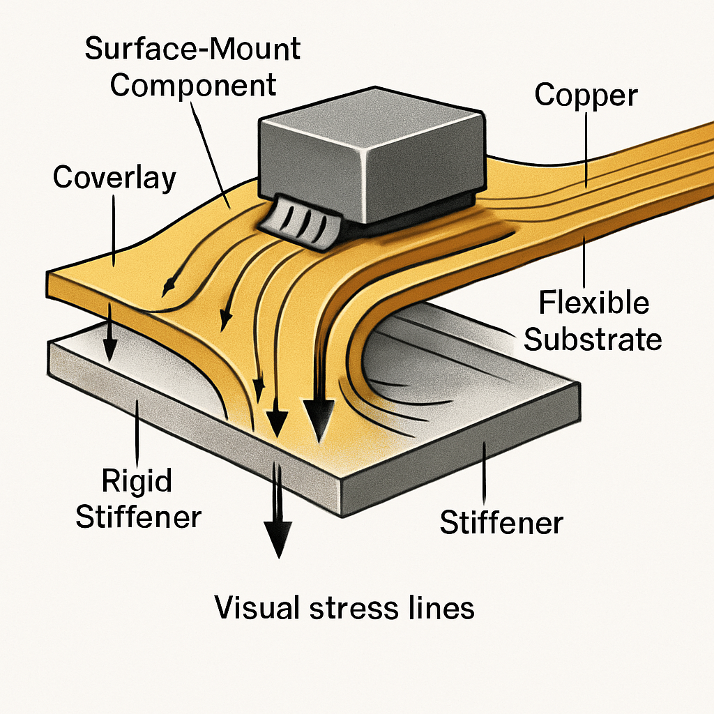
The most common requirement arises when mounting components directly to flexible regions. Surface-mount components—particularly larger devices like microcontrollers or connectors—create stress concentration points during flexing. Proper SMT assembly techniques for flexible substrates complement stiffener design to prevent component failure. The component’s rigid body acts as a fulcrum, focusing bending forces on the solder joints at its edges. A stiffener placed beneath and around the component eliminates this stress concentration by preventing flexing in that specific zone.
Connector interfaces present another critical application. Whether you’re working with ZIF connectors, FFC connectors, or board-to-board connections, the mechanical forces during mating and unmating require rigid support. Without stiffeners, repeated connector cycles can peel pads from the flexible substrate or crack traces near the connection point. The stiffener must extend beyond the connector footprint by at least 2-3mm on all sides, creating a transition zone that gradually distributes stress from the rigid connector area to the flexible circuit.
Interface zones between rigid and flexible sections in rigid-flex designs require particularly careful stiffener placement. These transition areas experience the highest mechanical stress during flexing, as the circuit bends from a rigid state to a flexible state within a very short distance. Placing stiffeners too close to the actual bend line creates stress risers—points of concentrated mechanical force that accelerate failure. IPC-2223, the industry standard for flexible circuit design, recommends maintaining a minimum distance of 1.5mm between the stiffener edge and the beginning of the bend radius.
Heavy component mounting presents additional challenges. When mounting components weighing more than a few grams on flexible substrates, the component’s mass can cause the circuit to droop or flex under its own weight, particularly during handling or assembly. Stainless steel stiffeners provide the necessary support to maintain flatness and prevent component shift during reflow soldering or subsequent manufacturing steps.
Material Selection for Optimal Performance
The choice of stiffener material significantly impacts both performance and cost. At Flex Plus, we guide our clients through this selection process by considering three primary factors: thermal requirements, mechanical load demands, and budget constraints.
FR4 represents the most common stiffener material, offering an excellent balance of rigidity, cost-effectiveness, and availability. As the same substrate material used in rigid PCBs, FR4 provides familiar mechanical properties and straightforward processing. Its coefficient of thermal expansion closely matches that of copper, minimizing stress during temperature cycling. For connector reinforcement and general component support in consumer electronics applications, FR4 typically provides sufficient performance at the lowest cost point.
Polyimide stiffeners serve specialized applications requiring extreme thinness or enhanced flexibility at the stiffener edges. At thicknesses as low as 50 microns, polyimide stiffeners reinforce ZIF connector areas in ultra-thin flex circuits while adding minimal bulk. The material’s inherent flexibility allows smoother transitions between reinforced and unreinforced areas, reducing stress concentration. Medical devices and wearable electronics frequently specify polyimide stiffeners to maintain comfort while providing necessary support.
Stainless steel offers the highest rigidity per unit thickness, making it ideal for applications requiring maximum dimensional stability with minimal added height. In high-vibration environments like automotive sensors or industrial control systems, stainless steel stiffeners prevent resonance-induced fatigue failure. The material’s thermal conductivity also provides a heat dissipation benefit for power components. However, designers must account for stainless steel’s higher cost and weight compared to polymer alternatives.
Bonding methods vary based on stiffener material and manufacturing process requirements. Pressure-sensitive adhesive (PSA) films provide quick assembly and require only lamination pressure, making them suitable for high-volume production. Acrylic-based PSAs offer good temperature resistance up to 120°C, sufficient for most consumer applications. For higher temperature requirements—such as automotive electronics exposed to engine compartment environments—thermally activated adhesives maintain bond integrity at temperatures exceeding 150°C.
At Flex Plus, our material consultation service helps designers select the optimal stiffener material and bonding method for their specific application. We consider factors including operating temperature range, vibration profiles, assembly requirements, and cost targets to recommend solutions that balance performance and manufacturability.
Design and Engineering Guidelines
Effective stiffener design requires attention to several critical parameters that determine both manufacturing success and long-term reliability.
Bend radius considerations form the foundation of stiffener placement. IPC-2223 establishes minimum bend radius guidelines as multiples of the total circuit thickness. For single-bend applications, the minimum radius should equal at least 6 times the total thickness. Dynamic applications requiring repeated flexing demand 12 to 20 times the thickness. The stiffener must never encroach on this bend zone. Creating a buffer distance of at least 1.5-2mm between the stiffener edge and the start of the bend radius prevents stress risers that accelerate flex circuit failure.
Stiffener size and thickness require careful calculation. The reinforcement must extend beyond component pads or connector footprints sufficiently to distribute forces effectively. As a general guideline, stiffeners should overlap component areas by 2-3mm on all sides for components up to 10mm in size, increasing to 4-5mm for larger components or high-stress applications. Thickness selection depends on the required rigidity—thicker stiffeners provide greater support but add bulk and reduce overall flexibility. Most applications use stiffeners ranging from 0.1mm to 0.5mm thickness.
Alignment accuracy becomes critical during manufacturing and assembly. In our fabrication drawings, we specify stiffener placement with tolerances of ±0.1mm for connector applications and ±0.2mm for general reinforcement. This precision ensures proper alignment with component pads, connector pins, and mounting features. Using registration holes or fiducial marks on both the flex circuit and stiffener helps maintain alignment during bonding.
Thermal considerations impact stiffener design in high-power applications. While stiffeners improve mechanical stability, they also affect heat dissipation paths. Metallic stiffeners like stainless steel or aluminum can enhance thermal management by spreading heat away from power components. Conversely, polymer stiffeners may trap heat, requiring careful thermal modeling for components dissipating more than 0.5W. At Flex Plus, our thermal management expertise—including our proprietary flexible heat dissipation flow channel technology—helps designers optimize stiffener placement for both mechanical and thermal performance. Understanding advanced flexible circuit materials like Pyralux provides additional thermal management options.
Electrical isolation requires attention when using metallic stiffeners near high-voltage circuits or sensitive analog signals. The adhesive layer typically provides adequate insulation for low-voltage applications, but high-voltage designs may require additional insulating layers or increased clearance. We recommend maintaining at least 1mm clearance between metallic stiffeners and exposed conductors in circuits operating above 100V.
Manufacturing and Assembly Considerations
Translating stiffener designs from concept to reliable production requires understanding manufacturing processes and quality control requirements.
Pre-cut stiffeners streamline assembly and ensure consistency across production volumes. At Flex Plus, we maintain close tolerances on stiffener dimensions—typically ±0.1mm—using precision die-cutting or CNC routing. This accuracy prevents alignment issues during bonding and ensures stiffeners don’t interfere with flex circuit features like via locations or trace routing.
Adhesive application technique significantly impacts bond quality and long-term reliability. Uniform adhesive thickness prevents air voids that compromise mechanical strength and create stress concentration points. We control adhesive thickness to within 25-50 microns through precise lamination pressure and temperature profiles. Too little adhesive creates inadequate bonding; too much causes adhesive squeeze-out that can contaminate component pads or interfere with subsequent assembly.
The bonding process itself requires careful parameter control. For thermally activated adhesives, we establish time-temperature profiles that fully cure the adhesive without damaging the flexible substrate. Typical processes use temperatures of 160-180°C with pressure of 3-5 bar for 30-60 minutes. Pressure distribution across the stiffener area must remain uniform to prevent edge lifting or center voids.
Quality inspection verifies proper stiffener placement and bonding before circuits proceed to component assembly. Visual inspection confirms alignment accuracy and checks for adhesive squeeze-out. Cross-sectional analysis on sample parts validates bond line uniformity and adhesive cure. At Flex Plus, our ISO 9001 certified quality management system ensures every stiffener application meets specification before the circuit advances to subsequent manufacturing steps.
Documentation proves essential for maintaining manufacturability across design revisions and future repairs. In our fabrication drawings, we define stiffener outlines on dedicated mechanical layers, specify material and thickness requirements, document adhesive types, and provide detailed assembly notes. This documentation enables consistent reproduction across prototype and production builds while facilitating future redesigns or maintenance activities.
Practical Takeaways for Reliable Flex Circuit Design
Implementing stiffeners effectively transforms flexible PCBs from fragile prototypes into robust, production-ready circuits that survive demanding applications. The key lies in viewing stiffeners not as add-on features but as integral design elements requiring early consideration in the layout process.
Start by identifying all high-stress zones in your design—connector areas, component mounting locations, and rigid-to-flex transitions. For complex designs requiring both rigid and flexible sections, consider rigid-flex PCB technology as an alternative to discrete stiffeners. Specify stiffeners for these zones during initial schematic capture rather than adding them as afterthoughts. This approach allows proper routing of traces and placement of vias to accommodate stiffener locations without compromising electrical performance.
Select stiffener materials based on your application’s specific requirements rather than defaulting to standard options. Consider the operating environment, assembly process, and cost targets to choose materials that provide necessary support without over-engineering the solution. Remember that material selection also impacts the bonding process and manufacturing lead time.
Work closely with your manufacturing partner to validate stiffener designs before committing to production. Selecting the right PCB assembly service partner ensures stiffener integration meets quality standards. At Flex Plus, our Design for Manufacturing support helps identify potential issues—like stiffeners placed too close to bend areas or inadequate overlap with component footprints—before they become costly manufacturing problems or field failures.
Document stiffener requirements thoroughly in fabrication drawings and assembly instructions. Clear documentation prevents misunderstandings during manufacturing and enables consistent quality across production batches. Include stiffener specifications in your STEP models to ensure mechanical fit with enclosures and mating components.
Engineering Partnership for Complex Flex Circuit Solutions
Flex PCB stiffener design represents just one aspect of creating reliable flexible circuits for demanding applications. The complexity of modern electronics—from electric vehicle battery management systems to implantable medical devices—requires comprehensive expertise spanning material science, mechanical engineering, and manufacturing process control.
At Flex Plus, our 20+ years of specialized experience in flexible and rigid-flex PCB manufacturing provides the foundation for successful project execution. Our ISO 13485, IATF 16949, and ISO 9001 certifications demonstrate our commitment to quality and process control across medical device, automotive, and industrial applications. Our engineering team offers design consultation from concept through production, helping optimize stiffener designs for manufacturability while meeting reliability requirements.
Our comprehensive capabilities—from rapid prototyping within one week to high-volume production with full assembly services—ensure consistent quality whether you’re validating a design concept or ramping to mass production. Direct communication with our production engineers eliminates the delays and quality inconsistencies common when working through brokers or trading companies.
For designers tackling the challenges of flexible circuit reliability in high-stress environments, strategic stiffener implementation provides proven protection against component failure. By understanding when to use stiffeners, selecting appropriate materials, and following established design guidelines, you transform flexible circuits into durable solutions that survive real-world operational demands.
Whether you’re developing next-generation automotive sensors, medical wearables, or industrial control systems, Flex Plus stands ready to support your flexible PCB requirements with technical expertise, certified manufacturing processes, and comprehensive engineering partnership from design through production.