
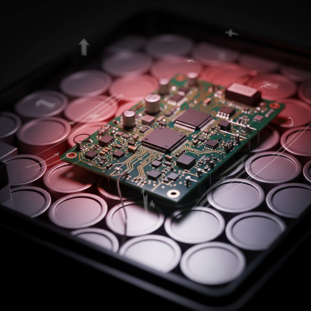
Every time you step into an electric vehicle, an invisible guardian watches over thousands of battery cells, making split-second decisions that could mean the difference between a safe journey and a catastrophic failure. This guardian is the Battery Management System—and at its heart lies a printed circuit board whose design precision directly determines whether your EV delivers on its promised range or leaves you stranded.
The rise of electric vehicles has transformed the automotive industry, but this transformation rests on a foundation that most drivers never see. While manufacturers tout battery capacity and charging speeds, the real story unfolds on specialized PCBs that orchestrate every electron flowing through your vehicle’s power system. These aren’t ordinary circuit boards. They operate in environments that would destroy conventional electronics—extreme temperatures, constant vibration, and electrical loads that could power entire households.
The Critical Role of BMS in Electric Vehicle Safety and Performance
Battery Management Systems serve as the brain and nervous system of every electric vehicle. They continuously monitor voltage across hundreds of individual cells, track temperature fluctuations, manage charging and discharging cycles, and intervene instantly when conditions threaten battery health or passenger safety. Without a properly designed BMS, lithium-ion batteries—which store energy at densities rivaling explosives—become unpredictable hazards.
The PCB design underlying these systems faces challenges unknown in traditional automotive electronics. Consider that a typical EV battery pack operates at 400 to 800 volts, yet the BMS must measure individual cell voltages with millivolt precision. This requires managing high-voltage isolation alongside sensitive analog circuitry on the same board—a balancing act that demands expertise built over decades, not months.
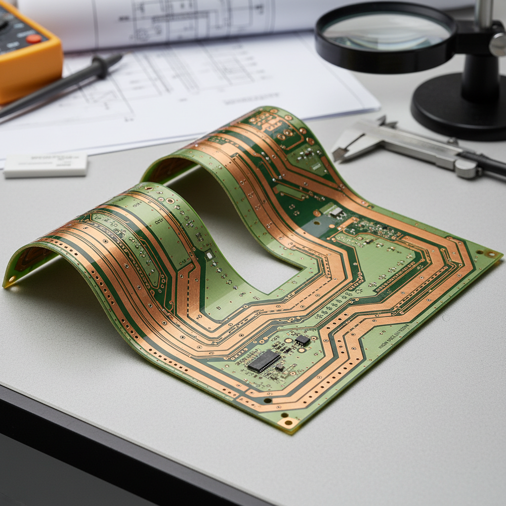
At FlexPlus, we’ve spent over 20 years refining flexible and rigid-flex PCB manufacturing specifically for these demanding applications. Our IATF 16949 certification reflects our understanding that automotive-grade quality isn’t just about meeting specifications—it’s about anticipating failure modes that emerge only after thousands of thermal cycles, millions of vibration events, and years of exposure to automotive environments.
Design Considerations That Separate Safe Systems from Dangerous Ones
High-voltage isolation stands as the first line of defense in BMS PCB design. When you’re routing traces carrying 800 volts mere millimeters from 3.3-volt microcontroller circuits, clearances and creepage distances must exceed IPC standards. Our engineering team applies design-for-manufacturing analysis specifically targeting isolation barriers, ensuring that production variations never compromise safety margins.
The automotive environment presents relentless challenges. BMS boards must function flawlessly at -40°C during Arctic winters and at +125°C in battery pack hot spots. Temperature cycling causes materials to expand and contract at different rates, creating mechanical stresses that can crack solder joints or delaminate PCB layers. This is where material selection becomes critical—not just choosing polyimide over FR-4, but understanding how specific substrate formulations respond to automotive thermal profiles.
Precision sensing represents another make-or-break design element. Every millivolt of measurement error compounds across hundreds of cells, potentially causing the BMS to miscalculate state-of-charge by significant percentages. This directly impacts vehicle range estimates and battery longevity. Achieving this precision requires meticulous attention to copper weight, trace geometry, and analog ground plane design—details that separate competent PCB manufacturers from true specialists.
Thermal management in BMS designs goes beyond adding heat sinks. Modern electric vehicles demand higher power densities, meaning more heat generation in smaller spaces. Our flexible circuit designs incorporate proprietary thermal pathway technology that moves heat away from critical components without sacrificing the mechanical flexibility needed for battery pack integration. This innovation emerged from years of solving real-world thermal failures, not from theoretical modeling alone.
Signal integrity concerns multiply in BMS applications because these systems must communicate reliably with vehicle networks while sitting in electrically noisy environments. High-current switching from motor controllers creates electromagnetic interference that can corrupt data or cause false readings. Effective PCB layouts incorporate strategic ground plane design, differential pair routing, and filtering—techniques that require understanding not just PCB design rules, but the physics of electromagnetic compatibility.
Safety compliance in BMS design extends beyond basic UL certification. As autonomous driving features proliferate, BMS systems increasingly require ASIL (Automotive Safety Integrity Level) ratings that mandate redundant microcontrollers, diversified sensing architectures, and fail-safe mechanisms. These requirements fundamentally shape PCB layouts, component selection, and testing protocols.
Electrical Sensing and Protection: The Technical Foundation
Every BMS begins with voltage measurement across individual cells and cell groups. This seemingly simple task becomes complex when you consider that cells may differ in voltage by only millivolts, yet the entire pack operates at hundreds of volts. The PCB must provide low-impedance paths for sense lines while maintaining high-voltage isolation—a challenge that influences trace routing, via placement, and connector design.
Current sensing in BMS applications must capture both slow continuous currents and rapid transients that occur during regenerative braking or acceleration. Shunt resistor placement on the PCB affects measurement accuracy, as does the thermal coefficient of copper traces carrying sense currents. Our design consultation services help engineers navigate these trade-offs, drawing on experience from over 2,500 customers across diverse EV applications.
Temperature monitoring provides critical safety protection, yet thermistor placement creates PCB layout dilemmas. Sensors must sit close enough to heat sources for rapid response, but not so close that PCB copper acts as a heat sink that distorts readings. Flexible PCB designs offer advantages here—they can conform to battery cell contours, placing sensors exactly where needed without the mechanical constraints of rigid boards.
Cell balancing control represents one of the most overlooked aspects of BMS PCB design. Passive balancing dissipates excess energy as heat, requiring PCBs that can handle sustained thermal loads without degrading. Active balancing transfers energy between cells, demanding precise timing control and robust gate drive circuits. The PCB layout directly impacts balancing effectiveness and efficiency—poorly designed boards can waste energy that should extend vehicle range.
Fault protection mechanisms must respond within microseconds when dangerous conditions emerge. This requires PCB designs that minimize loop inductance in high-current switching paths and provide clean, stable power to protection circuits. We’ve seen designs fail not because protection algorithms were inadequate, but because PCB layouts introduced delays or noise that prevented circuits from responding in time.
Architectural Excellence: Building Systems That Last
Power architecture in BMS PCBs must distribute energy efficiently while maintaining isolation and safety. This typically involves multiple power domains—high-voltage battery monitoring circuits, isolated gate drivers, low-voltage microcontroller supplies, and isolated communication interfaces. Each domain requires careful PCB planning to prevent crosstalk, minimize noise, and ensure reliable operation.
Communication interfaces connect the BMS to the vehicle’s central computer, typically using CAN bus, LIN bus, or more recently, automotive Ethernet. The PCB must route these differential signals with controlled impedance while protecting them from electrical transients that regularly occur in automotive systems. Flexible PCBs excel in this application because they can be routed through mechanically constrained spaces without compromising signal integrity.
Noise management separates functional designs from truly robust ones. Ground plane strategy becomes paramount—should you use a single unified ground or split analog and digital grounds? The answer depends on circuit architecture, but the implementation lives in PCB layout. Strategic via placement, guard traces, and filtering components must be positioned where they provide maximum benefit without consuming excessive board space.
Mechanical design considerations often receive insufficient attention in BMS PCB planning. Battery packs undergo constant vibration from road conditions, and mounting hardware must not create stress concentrations that lead to PCB failure. Our rigid-flex PCB technology addresses this by eliminating connectors—87% fewer interconnection points means 87% fewer potential failure sites. Designs can incorporate flexible sections that absorb mechanical stress while maintaining rigid sections that provide stable mounting platforms for critical components.
Manufacturing Excellence and Quality Assurance
Testing and validation of BMS PCBs cannot follow standard consumer electronics protocols. These boards must undergo thermal cycling, vibration testing, high-voltage isolation verification, and functional testing under load conditions that simulate worst-case automotive scenarios. At FlexPlus, our full in-house control over production enables testing at every manufacturing stage, not just final inspection.
Traceability requirements in automotive manufacturing demand that every BMS PCB be traceable to specific material lots, production dates, and test results. This isn’t bureaucracy—when a field issue emerges years after production, traceability enables rapid identification of affected units and root cause determination. Our ISO 9001 and IATF 16949 certifications ensure these systems are embedded in our processes, not added as afterthoughts.
Cost considerations in BMS PCB design require balancing initial manufacturing expenses against lifetime reliability. Cheaper substrate materials or simplified layouts may reduce unit costs, but field failures in automotive applications carry enormous financial and reputational consequences. The true cost calculus must include warranty expenses, recall risks, and brand damage—factors that favor working with experienced manufacturers who understand these trade-offs.
Future-Proofing BMS Designs for Evolving Technology
Integration with vehicle systems continues to deepen as electric vehicles add features like bidirectional charging, vehicle-to-grid capabilities, and battery-as-a-service business models. BMS PCB designs must anticipate these trends by incorporating additional communication interfaces, enhanced processing capabilities, and security features that protect against cyber threats. The flexible PCB architectures we manufacture adapt more readily to these evolving requirements than rigid boards locked into legacy form factors.
Evolving safety norms will continue raising the bar for BMS reliability. As autonomous driving becomes mainstream, battery systems may require certification to safety levels previously reserved for aviation applications. PCB designs must incorporate redundancy, self-diagnostics, and graceful degradation capabilities that allow vehicles to reach safe states even when components fail. Planning for these requirements today prevents costly redesigns tomorrow.
Technological advancements in battery chemistry—solid-state batteries, silicon anodes, lithium-metal cells—will impose new demands on BMS PCBs. Sensing requirements may change, thermal profiles will shift, and form factors will evolve. Manufacturers who understand these trajectories and build flexibility into their designs will avoid obsolescence as the industry advances. Our 20+ years of experience across diverse applications positions us to anticipate these changes and guide customers through transitions.
Practical Takeaways for EV Development Teams
Precision in BMS PCB design is not optional—it directly determines whether your electric vehicle delivers on safety promises and range specifications. Every design decision, from substrate selection to trace routing, compounds through the system affecting measurement accuracy, thermal performance, and long-term reliability. Engaging with specialized manufacturers early in the design process prevents costly iterations and accelerates time-to-market.
Engineers should prioritize Design for Manufacturing analysis specifically targeting BMS requirements. Generic DFM tools miss automotive-specific concerns like thermal cycling performance, high-voltage isolation verification, and long-term reliability in harsh environments. Working with certified manufacturers who provide comprehensive DFM feedback reduces prototype iterations and identifies potential failures before production.
Material consultation provides value that extends far beyond cost comparison. Understanding how different polyimide formulations perform under automotive thermal cycling, or how copper weight affects both current capacity and flexibility, enables informed trade-offs between performance, reliability, and cost. These consultations draw on decades of manufacturing experience that no design team can replicate internally.
Direct communication with production engineers eliminates the quality inconsistencies and delays that plague broker-mediated manufacturing. When design questions arise during production—and they always do—direct access to the engineers building your boards ensures rapid resolution with minimal impact on schedules. This advantage becomes critical in automotive programs where launch delays carry severe financial penalties.
The path from concept to production-ready BMS requires partners who combine technical expertise, manufacturing capability, and quality systems proven in automotive applications. At FlexPlus, we’ve built our reputation over two decades by solving the challenges others find impossible—whether that’s ultra-thin flexible designs that fit in constrained battery pack spaces, thermal management solutions for high-power applications, or rigid-flex architectures that eliminate reliability-limiting connectors.
Your electric vehicle’s success depends on decisions being made today in BMS PCB design. Choose partners who understand that precision isn’t just about hitting specifications—it’s about anticipating failure modes, designing for manufacturability, and delivering reliability that protects both passengers and your brand reputation for years to come.