
When engineers at a leading automotive sensor manufacturer faced a 34% failure rate in their cable-to-board connections, they turned to rigid-flex PCB technology. Within six months of redesigning their assembly with integrated rigid-flex circuits, their failure rate dropped to just 4.4%—an 87% reduction that translated to millions in warranty cost savings and enhanced brand reputation.
This dramatic improvement isn’t unique. Across industries from electric vehicles to medical devices, engineers are discovering that rigid-flex PCBs offer more than just space savings—they fundamentally transform product reliability by eliminating the weakest points in electronic assemblies: the interconnections.
Understanding Rigid-Flex PCBs: Where Flexibility Meets Structural Integrity
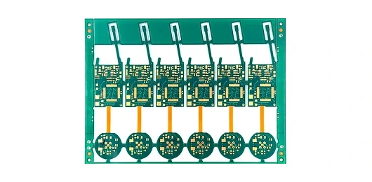
Rigid-flex PCBs represent a hybrid technology that combines rigid printed circuit boards with flexible circuit sections into a single integrated unit. Unlike traditional assemblies that rely on cables, connectors, or multiple separate boards, rigid-flex designs use flexible polyimide substrates that transition seamlessly into rigid FR-4 sections.
The composition typically features flexible layers made from polyimide film with copper conductors, laminated together with rigid board sections using specialized bonding materials. This integration creates a three-dimensional circuit structure that can bend, fold, or twist to fit complex enclosures while maintaining the component mounting stability of traditional rigid boards.
For procurement specialists and engineering teams in automotive, medical device, and aerospace sectors, this technology addresses a critical challenge: traditional assembly methods create numerous potential failure points. Every connector, every cable junction, and every solder joint between separate boards represents a reliability risk. A typical automotive sensor assembly might contain 15-20 interconnection points—each one a potential source of electrical failure, especially under vibration, thermal cycling, or mechanical stress.
Rigid-flex technology eliminates up to 87% of these interconnection points by integrating what would be multiple components into a single circuit. This isn’t just a marginal improvement—it represents a fundamental shift in how engineers approach assembly reliability for high-volume production.
Core Design Principles: Engineering for Reliability from Day One
The dramatic failure rate reductions achieved with rigid-flex PCBs don’t happen by accident. They result from careful attention to three critical design elements: stackup planning, bend radii optimization, and flex-to-rigid transitions.
Stackup planning determines how layers are arranged throughout the rigid and flexible sections. Unlike rigid PCBs where layers remain constant, rigid-flex designs require engineers to carefully plan where layers transition. A poorly planned stackup creates stress concentration points that lead to copper cracking, delamination, and electrical failures. Best practice involves placing conductor layers symmetrically around the neutral axis in flex sections, ensuring that tensile and compressive forces balance during bending. Understanding these fundamental material properties guides effective stackup design. For a four-layer rigid-flex design, this typically means routing critical signals on inner layers within the flex region, protected by outer ground or power planes.
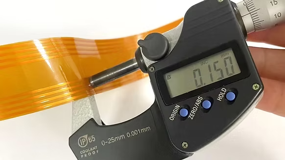
Bend radius optimization directly impacts mechanical reliability. IPC-2223 standards specify minimum bend radii based on board thickness and application type—typically 10 times the total thickness for dynamic flexing applications, or 6 times for static installations. However, experienced engineers often design with more conservative ratios. A flex section with 0.2mm total thickness should maintain at least a 2mm bend radius for dynamic applications. Sharp bends concentrate stress and accelerate conductor fatigue. Engineers working on wearable devices or robotic applications, where circuits experience thousands of flex cycles, pay particular attention to this parameter. Real-world testing at certified manufacturers often reveals that doubling the minimum specified bend radius can extend flex life by 5-10 times.
Flex-to-rigid transitions represent the most critical design zones. These areas experience the highest mechanical stress during assembly and operation. Design rules for these transitions are specific and unforgiving: conductors should never terminate at the transition line, stiffeners should end at least 1mm before the flex region begins, and coverlay or soldermask should overlap the transition by at least 0.5mm to prevent stress concentration. Teardrops on vias near transitions help distribute mechanical loads and prevent pad lifting during flexing.
For R&D engineers developing new products, understanding these principles early in the design phase prevents costly redesigns. A medical device manufacturer recently shared that implementing proper transition zone design in their initial prototype eliminated two redesign cycles, saving four months of development time and reducing prototype costs by 60%.
Material Selection: Balancing Flexibility, Durability, and Performance
Material choices in rigid-flex designs directly influence product reliability and manufacturing success. The flexible sections typically use polyimide-based laminates—specifically because polyimide maintains electrical and mechanical properties across extreme temperature ranges (-200°C to +400°C) and offers exceptional tear resistance.
Two main types of polyimide laminates dominate the industry: adhesive-based and adhesiveless constructions. Adhesive-based laminates use acrylic or epoxy adhesives to bond copper to polyimide film. These materials offer good flexibility and lower cost, making them suitable for consumer electronics applications with moderate reliability requirements. However, the adhesive layer can degrade under prolonged high-temperature exposure or absorb moisture, potentially affecting electrical properties in demanding environments.
Adhesiveless laminates, where copper is directly deposited onto polyimide without an adhesive layer, provide superior performance for aerospace, medical, and automotive applications. The elimination of adhesive improves thermal stability, reduces moisture absorption, and enhances reliability under extreme conditions. When an aerospace contractor needed rigid-flex circuits for satellite communication systems operating in harsh space environments, adhesiveless construction was non-negotiable—the adhesive layer’s outgassing potential and thermal expansion characteristics posed unacceptable risks. These critical material decisions require deep manufacturing expertise.
Stiffeners play a crucial supporting role in rigid-flex assemblies. These materials—typically FR-4, polyimide film, or stainless steel—are bonded to flexible sections that require temporary or permanent rigidity for component mounting or connector attachment. The choice depends on application requirements: FR-4 stiffeners offer good dimensional stability and are easy to machine, making them ideal for component mounting areas. Polyimide stiffeners maintain flexibility while adding controlled stiffness, useful for sections that need support during assembly but must flex during operation. Stainless steel stiffeners, though more expensive, provide superior thermal dissipation and mechanical protection for high-reliability applications.
Thermal management considerations affect material selection significantly. High-power LED applications or automotive battery management systems generate substantial heat that must be dissipated through the circuit structure. Engineers working on these applications might specify thicker copper layers (70μm instead of 35μm) in heat-intensive regions, or incorporate metal core stiffeners that act as heat sinks. The material stackup must balance thermal conductivity requirements with the need to maintain flexibility in dynamic sections.
For procurement teams evaluating suppliers, understanding material capabilities helps assess manufacturing expertise. A manufacturer offering only adhesive-based constructions may lack the process control necessary for aerospace or medical applications requiring IATF 16949 certification or ISO 13485 certification.
Manufacturing Process: Precision in Complex Integration
The manufacturing complexity of rigid-flex PCBs explains both their reliability advantages and their cost premium compared to rigid-only designs. The process integrates rigid PCB fabrication techniques with flexible circuit manufacturing, requiring specialized equipment and process control.
Production begins with inner layer processing—creating the circuit patterns on both rigid and flexible substrates separately. Flexible layers receive copper patterns through photolithography and etching, similar to rigid boards, but with critical differences in handling. Polyimide’s dimensional stability differs from FR-4, requiring adjusted processing temperatures and pressures to prevent material distortion.
The lamination process represents the most critical and complex manufacturing step. Unlike rigid PCB lamination where all layers have similar thermal expansion characteristics, rigid-flex lamination must bond materials with different expansion coefficients without creating internal stress. Manufacturers use specialized lamination cycles with precise temperature ramps, dwell times, and pressure profiles to achieve proper bonding while preventing delamination risks. A typical cycle might involve pre-heating to 170°C, then increasing to 185°C for bonding, with carefully controlled cooling to room temperature—all while maintaining precise pressure uniformity across the panel.
Via formation in rigid-flex designs presents unique challenges. Through-hole vias must traverse both rigid and flexible sections, requiring precise drill depth control to avoid damaging flexible layers. Manufacturers employ laser drilling for microvias in high-density designs, achieving hole diameters down to 0.1mm with positional accuracy within ±0.05mm. The plating process must achieve uniform copper distribution through vias crossing material interfaces where plating dynamics differ significantly.
Controlled impedance requirements add another layer of complexity. Signal integrity in high-speed designs demands precise impedance control, typically ±10% tolerance. In rigid-flex circuits, impedance varies between rigid and flexible sections due to different dielectric constants and layer thicknesses. Experienced manufacturers compensate by adjusting trace widths at transitions, ensuring impedance continuity throughout the signal path. Testing validates impedance across the entire circuit, not just in isolated sections.
Common manufacturing pitfalls include improper registration between layers at flex-to-rigid transitions, inadequate stiffener adhesion leading to delamination during assembly, and copper cracking at bend regions due to excessive stress during processing. Quality manufacturers implement design-for-manufacturing reviews before production, identifying potential issues like insufficient clearance around plated through-holes in flex regions or conductor routing that violates minimum bend radius requirements.
For project managers overseeing product development, understanding these manufacturing complexities helps set realistic timelines and expectations. Partnering with experienced certified flex PCB suppliers mitigates these production risks. A first-article rigid-flex prototype typically requires 2-3 weeks for fabrication compared to 1 week for rigid-only designs, reflecting the additional process steps and inspection requirements.
Industry Standards: Ensuring Reliability Through Compliance
Design and manufacturing of rigid-flex PCBs for high-reliability applications must align with industry standards that define performance expectations and testing requirements. Two standards form the foundation: IPC-2223 for design guidelines and IPC-6013 for qualification and performance specifications.
IPC-2223 provides comprehensive design guidance specific to flexible and rigid-flex circuits. It addresses mechanical layout principles, including bend radius requirements, conductor routing rules in flex areas, and stiffener placement guidelines. The standard specifies that conductors in dynamic flex areas should follow curves rather than straight lines when the flex bends perpendicular to conductor direction—this seemingly minor detail significantly impacts flex life. IPC-2223 also defines clearance requirements: coverlay must extend at least 0.15mm beyond the outer conductors, and stiffeners should maintain 1-1.5mm clearance from flex regions to prevent stress concentration.
For engineers designing their first rigid-flex assembly, IPC-2223 sections on transition zone design prove invaluable. The standard provides specific guidance on how rigid and flexible sections should interface, including recommendations for gradual transitions using additional stiffening layers rather than abrupt material changes that concentrate stress.
IPC-6013 defines three performance classes for flexible and rigid-flex circuits:
- Class 1 (General Electronic Products): Suitable for consumer applications where cosmetic imperfections are acceptable and the primary requirement is functionality
- Class 2 (Dedicated Service Electronic Products): Covers most commercial and industrial applications, requiring enhanced cosmetic and reliability performance
- Class 3 (High Performance Electronic Products): Specifies the most stringent requirements for aerospace, military, and medical applications where continued performance and extended life are critical
The class designation affects inspection criteria, testing requirements, and acceptable defect levels. A Class 3 rigid-flex design for an implantable medical device undergoes thermal cycling testing (-55°C to +125°C for 500 cycles), vibration testing (20G for specific frequencies), and microsectioning analysis to verify layer adhesion and via quality. Class 2 requirements are less stringent but still demand comprehensive testing to ensure reliability in commercial applications.
For procurement specialists evaluating manufacturing partners, certifications matter significantly. A manufacturer claiming rigid-flex capabilities should hold relevant certifications: IATF 16949 for automotive applications, ISO 13485 for medical devices, and AS9100 for aerospace. These certifications verify that the manufacturer maintains process controls, documentation, and quality systems necessary for high-reliability production.
Quality assurance teams should verify that suppliers perform critical tests including peel strength measurement (adhesion between layers), thermal stress testing, and electrical continuity verification across temperature extremes. IPC-6013 Class 3 specifications require peel strength of at least 1.0 N/mm for flexible circuits—values below this threshold indicate potential delamination risks under operating conditions.
Design-for-Manufacturing Checklist: Practical Implementation Guide
Translating theoretical knowledge into reliable production requires systematic attention to design details. This checklist distills 20+ years of manufacturing experience into actionable guidance for engineering teams:
Mechanical Design Considerations:
- Specify bend radii at least 10× total thickness for dynamic applications, 6× for static installations
- Route all conductors perpendicular to the primary bend axis in flex regions
- Maintain 1mm minimum clearance between stiffeners and flex zone boundaries
- Use radiused corners (minimum 1.5mm radius) instead of sharp angles in flex outlines
- Design flex sections with symmetrical layer stackups to balance stress during bending
Electrical Design Requirements:
- Keep trace widths consistent through transitions; if impedance matching requires width changes, implement them gradually over 3-5mm distance
- Place all vias at least 1mm away from flex-to-rigid transition lines
- Implement teardrops on vias and pads in flex regions to distribute mechanical stress
- Design controlled impedance traces with ±10% tolerance accounting for material differences between rigid and flexible sections
- Avoid routing high-frequency signals through areas experiencing repeated flexing
Material Selection Guidelines:
- Specify adhesiveless polyimide laminates for applications requiring UL approval or operating above 150°C
- Select copper weight based on current requirements: 35μm (1oz) for signal layers, 70μm (2oz) for power distribution
- Specify coverlay thickness appropriate to application: 25μm for maximum flexibility, 50-75μm for enhanced protection
- Choose stiffener materials matching thermal expansion characteristics of adjacent regions
Manufacturing and Quality Considerations:
- Limit layer count in flex sections to 4 layers maximum; more layers reduce flexibility and increase failure risk
- Maintain minimum 0.15mm clearance between coverlay edge and outer conductors
- Design panel borders allowing 5mm clearance for processing tooling holes
- Specify acceptance criteria aligned with IPC-6013 Class appropriate to application (Class 2 for commercial, Class 3 for medical/aerospace)
- Request test coupons on production panels for impedance verification and cross-sectional analysis
Flex Life and Reliability:
- Calculate expected flex cycles over product lifetime; designs exceeding 100,000 cycles require specialized conductor patterns and materials
- Specify environmental testing requirements: temperature range, humidity exposure, vibration profiles
- Consider moisture sensitivity level (MSL) requirements for storage and handling
- Design with stress relief features in high-flex areas: wider conductor spacing, additional stiffener support in transition zones
Testing and Validation:
- Require impedance testing on controlled impedance traces with TDR analysis showing continuity through transitions
- Specify thermal cycling tests appropriate to operating environment (-55°C to +125°C for automotive applications)
- Request microsection analysis of first articles to verify layer adhesion, via quality, and registration accuracy
- Implement electrical testing validating continuity and isolation at temperature extremes
This checklist reflects the integration of certified manufacturing excellence with practical engineering experience—the foundation of reliable rigid-flex designs that achieve the 87% reduction in assembly failures that leading manufacturers report. When engineering teams collaborate with certified manufacturers holding ISO 9001, IATF 16949, and ISO 13485 certifications, these guidelines transform from theoretical best practices into production realities that deliver consistent quality from prototype through high-volume manufacturing.
The strategic integration of rigid-flex technology represents more than incremental improvement—it fundamentally reshapes how engineers approach electronic assembly reliability. By eliminating interconnection points, optimizing mechanical design, and adhering to industry standards, today’s engineering teams are achieving reliability levels that seemed impossible with traditional assembly methods just a decade ago.