
When you’re planning a product destined for high-volume manufacturing, choosing between flexible PCBs (FPCBs) and traditional rigid PCBs isn’t just a technical decision—it’s a strategic one that impacts your bottom line for years to come. The choice determines your assembly costs, product reliability, design flexibility, and ultimately, your return on investment.
Think of it this way: traditional PCBs are like the reliable foundation of a house—stable, predictable, and thoroughly understood. FPCBs, on the other hand, are like the flexible joints in a human body—they move, adapt, and enable entirely new possibilities. But which architecture truly delivers better ROI when you’re manufacturing thousands or millions of units?
The answer isn’t always straightforward. While traditional PCBs dominate in cost-per-unit for simple applications, FPCBs can dramatically reduce total system costs by eliminating connectors, cables, and assembly steps. The key is understanding the mechanical, electrical, and manufacturing differences that make each architecture excel in specific scenarios.
The Mechanical Reality: Bendability Meets Stability
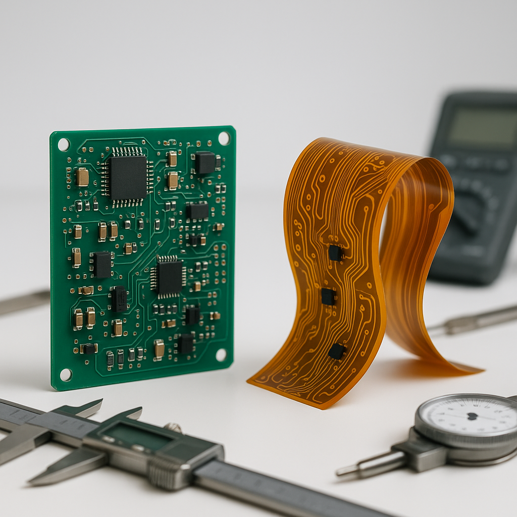
The most obvious difference between FPCB and traditional PCB lies in their physical nature. Traditional rigid PCBs use FR-4 fiberglass substrate—a sturdy material that maintains its shape under stress. These boards typically range from 0.4mm to 3.2mm in thickness, providing mechanical stability that’s ideal for mounting components and securing assemblies.
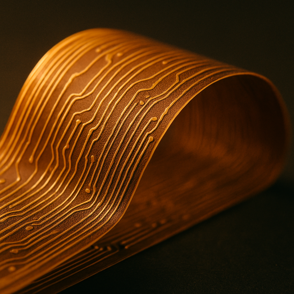
FPCBs take a fundamentally different approach. Built on polyimide film substrates, they can bend up to 360 degrees and withstand over 500 million flex cycles in dynamic applications. A flexible circuit occupies roughly 10% of the space compared to its rigid equivalent, making it transformative for products where every millimeter matters.
But here’s where it gets interesting for high-volume manufacturing: bend radius management becomes critical. An improperly designed bend can fail in just thousands of cycles instead of millions. The minimum bend radius typically equals ten times the total thickness for dynamic applications, or three times for static bends. This isn’t just a design guideline—it’s the difference between a product that lasts and one that fails in the field.
For products requiring both stability and flexibility, rigid-flex PCBs offer an integrated solution. These boards combine rigid sections for component mounting with flexible interconnects, eliminating up to 87% of interconnection points compared to cable-based assemblies. This reduction translates directly to improved reliability—fewer connections mean fewer potential failure points.
Consider a wearable medical device. The main processing unit needs a stable platform for sensitive components, but the sensor array must conform to body contours. A rigid-flex solution provides both capabilities in a single assembly, reducing manufacturing complexity while improving product performance.
Electrical Performance: When Signals Travel Through Flexible Paths
Electrical considerations reveal deeper differences between these architectures. Traditional PCBs excel at impedance control because their rigid structure maintains consistent trace geometry. For high-speed signals requiring 50-ohm or 100-ohm differential pairs, this stability simplifies design and manufacturing.
FPCBs introduce unique challenges for signal integrity. When a flexible circuit bends, the trace geometry changes slightly, potentially affecting impedance. For DC or low-frequency signals, this variation is negligible. But for high-speed digital signals or RF applications, designers must account for impedance variations during flexing.
The solution lies in controlled impedance design specifically tailored for flexible circuits. By carefully selecting trace dimensions and stackup configurations, engineers can maintain signal integrity even during dynamic flexing. Modern FPCBs achieve minimum trace widths of 0.05mm with 0.05mm spacing—enabling high-density interconnect designs that rival rigid board capabilities.
Here’s a real-world scenario: In optical transceiver modules, signals travel at multi-gigabit speeds through extremely compact spaces. Traditional rigid PCBs would require multiple boards connected by cables, introducing signal degradation at each connection. A well-designed FPCB eliminates these connections entirely, improving signal integrity while reducing size by 60% or more.
Thermal management also differs significantly. Rigid PCBs dissipate heat through copper planes and thermal vias connecting to heat sinks. FPCBs have limited thermal mass, making heat dissipation more challenging. Advanced solutions include embedding thermal pathways within flexible circuits—a breakthrough technology that enables heat flow without sacrificing flexibility.
Materials and Manufacturing: From Substrate to Finished Product
The manufacturing processes for FPCB versus traditional PCB reflect their fundamental architectural differences. Traditional rigid PCBs start with copper-clad FR-4 laminate sheets. The standard subtractive process involves applying photoresist, exposing the circuit pattern, developing, etching away unwanted copper, and stripping the resist—a well-established workflow with high yields and predictable costs.
FPCB manufacturing introduces additional complexity. The flexible substrate—typically polyimide film—requires specialized handling throughout fabrication. Instead of solder mask, FPCBs often use coverlay, a flexible film bonded to protect the circuitry. This coverlay must be carefully registered and laminated to avoid wrinkles or bubbles that could compromise performance.
Stiffeners play a crucial role in flexible circuit manufacturing. These rigid backing materials attach to specific areas where components mount or connectors attach, providing local rigidity without eliminating overall flexibility. The stiffener material selection—whether FR-4, polyimide, or stainless steel—depends on thermal requirements, thickness constraints, and cost targets.
For high-volume production, the choice between roll-to-roll and panel processing significantly impacts economics. Roll-to-roll processing excels for long, narrow designs like those used in automotive lighting or industrial sensors. This method achieves higher utilization rates and lower per-unit costs for suitable geometries. Panel processing provides more flexibility for mixed designs but with slightly higher material waste.
Multilayer FPCB construction adds another dimension of complexity. Creating a three-layer or four-layer flexible circuit requires precise registration between layers and careful control of adhesive thickness. Each additional layer increases both capability and cost, making layer count optimization critical for ROI.
The rigid-flex manufacturing process combines these approaches. Rigid sections use standard FR-4 stackup, while flexible sections use polyimide. The transition zones require careful design to manage stress concentration—poor transition design is a leading cause of field failures. Manufacturing these hybrid structures demands specialized equipment and expertise, which is why partner selection becomes critical for high-volume success.
Design Implications: Engineering for Manufacturing Success
Designing for FPCB versus traditional PCB requires fundamentally different approaches. Traditional rigid PCB design is well-documented, with extensive design rule checking (DRC) tools and established best practices. Designers can confidently place components at 0.4mm pitch or tighter, knowing that standard assembly equipment handles these densities routinely.
FPCB design demands additional considerations from the concept phase. Enclosure fit becomes paramount—the flexible circuit must route through available space without exceeding minimum bend radii or creating stress points. Engineers must map the three-dimensional path early in the design cycle, not as an afterthought.
Bend radius management affects component placement directly. Active components and rigid connectors must locate in non-bending zones, often requiring stiffener backing. This constraint influences both PCB layout and mechanical enclosure design. For products with moving parts—like flip phones or foldable devices—the flex zone must accommodate millions of cycles without fatigue.
Thermal management strategies differ substantially. While rigid PCBs can route heat through copper pours and thermal vias, FPCBs need creative solutions. Strategically placed stiffeners can act as heat spreaders. Copper weight selection becomes a thermal tool—heavier copper improves both current capacity and heat dissipation but reduces flexibility.
Assembly considerations also diverge. Traditional PCBs mount to enclosures using standard standoffs and screws. FPCBs often attach using pressure-sensitive adhesives, requiring careful surface preparation and bonding process control. The assembly sequence must prevent accidental bending during component placement and soldering.
For rigid-flex designs, the transition from rigid to flexible sections requires special attention. Sharp corners concentrate stress and invite cracking. Best practice calls for generous radiusing at all transitions, typically 1.5mm minimum radius. The flexible portion should extend at least 2-3mm beyond the rigid section to distribute stress gradually.
Cost Analysis: Initial Investment Versus Long-Term Value
Understanding the true cost comparison between FPCB and traditional PCB requires looking beyond per-unit board costs. Traditional rigid PCBs enjoy significant cost advantages for simple, single-layer designs in moderate quantities. A basic two-layer rigid PCB might cost $2-5 per unit in volumes of 10,000 pieces—a baseline that’s hard to beat.
FPCBs start at higher per-unit costs due to material expenses and specialized processing. A comparable two-layer flexible circuit might run $8-15 per unit at similar volumes. On the surface, this appears to favor rigid PCBs decisively. But that calculation ignores the system-level implications.
Consider a product requiring three rigid PCBs interconnected by cables and connectors. The boards might cost $15 total, but add $5 for cables, $8 for connectors, plus assembly labor to install and test each connection. The total approaches $30. A single rigid-flex assembly eliminating those interconnects might cost $25—achieving 15% savings while improving reliability dramatically.
Prototyping costs tell a different story. Traditional rigid PCB prototypes arrive quickly at reasonable costs—$200-500 for a typical design. FPCB prototypes cost more, typically $800-2000 for comparable complexity, due to specialized tooling and lower volume economics. This higher prototype cost extends development budgets but often pays back through reduced assembly complexity.
At mass production volumes, the economics shift again. Once tooling is amortized across 100,000+ units, per-unit costs drop substantially for both technologies. FPCBs can approach rigid board pricing when designs eliminate multiple boards and interconnects. The savings in assembly labor, testing time, and improved yields often tip the ROI calculation in favor of flexible solutions.
Yield considerations impact total costs significantly. Traditional rigid PCBs achieve 95-98% yields routinely in volume production. FPCBs face more variables—coverlay registration, adhesive control, flex testing—that can reduce yields to 90-95% until processes mature. Working with an experienced manufacturer like Flex Plus, with 20+ years specializing in flexible circuits, ensures yields approach rigid board levels even in early production.
Testing and inspection costs differ as well. Rigid PCBs undergo standard electrical testing and automated optical inspection (AOI). FPCBs require additional flex testing to verify mechanical performance, adding $0.50-1.50 per unit depending on complexity. This testing investment prevents field failures that would cost far more to address.
When to Choose FPCB or Traditional PCB
Selecting the right architecture depends on specific project requirements beyond simple cost comparison. Traditional rigid PCBs remain optimal when your design features:
Static mounting requirements: If the board simply bolts into an enclosure without movement, rigidity provides advantages. Standard mounting hardware, familiar assembly processes, and well-understood reliability make rigid boards the default choice.
Large component arrays: High-power processors, complex memory arrays, and densely packed surface-mount components perform best on stable rigid substrates. The mechanical stability simplifies thermal management and prevents component stress during assembly.
Cost-sensitive, high-volume consumer products: For products where every cent matters and the design doesn’t benefit from flexibility, rigid PCBs deliver the lowest total cost. Think simple appliances, basic consumer electronics, or any product where form follows established patterns.
Standard geometries: If your board is rectangular, fits conventional dimensions, and doesn’t require creative routing, rigid PCB economies of scale work in your favor.
FPCBs become the superior choice when your product demands:
Enclosure constraints: Wearable devices, medical implants, and compact consumer electronics often lack space for rigid boards and cables. FPCBs route through tight spaces, fold around corners, and occupy minimal volume.
Weight reduction: Aerospace, drone, and portable device applications benefit from FPCB’s 90% weight reduction compared to rigid-flex cable assemblies. Every gram eliminated improves performance or extends battery life.
Movement requirements: Products with sliding, folding, rotating, or flexing mechanisms need FPCBs. Laptop hinges, foldable phones, flip-style cameras, and articulating arms all rely on flexible circuits to maintain electrical connections during motion.
Reliability in harsh environments: Flexible circuits eliminate connectors that fail from vibration and shock. Military, automotive, and industrial applications increasingly specify FPCBs precisely because they withstand conditions that defeat cable assemblies.
Three-dimensional geometries: When your product requires circuits to wrap around cylinders, conform to curves, or route through complex three-dimensional spaces, FPCBs provide the only practical solution.
Rigid-flex combinations optimize ROI when you need both capabilities—stable platforms for main processing coupled with flexible interconnects. This architecture eliminates connectors while providing mounting stability, making it ideal for advanced automotive systems, aerospace controls, medical devices, and high-end consumer electronics.
Making the Decision: Beyond Technical Specifications
Choosing between FPCB and traditional PCB for high-volume manufacturing ultimately comes down to understanding your specific application requirements and lifecycle economics. The decision framework should consider:
Total system cost: Account for boards, interconnects, assembly labor, testing, and field reliability—not just per-unit board pricing.
Reliability requirements: Calculate the cost of field failures, warranty claims, and brand reputation damage. In critical applications, FPCB’s superior reliability often delivers overwhelming ROI despite higher unit costs.
Production volume and timeline: Higher volumes amortize FPCB tooling costs across more units, improving economics. Consider your production ramp schedule and lifetime volume projections.
Supply chain complexity: Working with a full-service manufacturer like Flex Plus that controls the complete process from raw material to final assembly simplifies logistics and quality management compared to coordinating multiple suppliers.
Innovation requirements: If your product differentiates through compact design, innovative form factors, or superior reliability, FPCB enables capabilities impossible with traditional architectures.
The best partner brings more than manufacturing capability. They offer certified processes (ISO 9001, ISO 13485, IATF 16949), comprehensive design support from concept through production, and proven experience across industries from automotive to medical devices. Direct access to production engineers eliminates communication delays and enables rapid design iteration.
Whether you choose FPCB, traditional PCB, or rigid-flex solutions, the key to ROI lies in making an informed decision based on complete system economics, reliability requirements, and manufacturing partnership. The right choice balances immediate costs against long-term value, enabling products that meet performance targets while delivering sustainable profitability.
Flex Plus (Xiamen) Co., Ltd brings 20+ years of specialized expertise in flexible and rigid-flex PCB solutions, from ultra-thin 25-micron designs to innovative TPU circuits for next-generation wearables. Our end-to-end manufacturing control, advanced COB integration capabilities, and commitment to certified quality ensure your high-volume product achieves optimal ROI through superior circuit board architecture tailored precisely to your application requirements.