
When your electric vehicle startup pitches its innovative battery management system to automotive giants, or when your medical device needs FDA approval, the flexible PCB material choice you made months ago suddenly becomes the difference between success and costly redesign. Material selection isn’t just a checkbox in your design process—it’s a strategic decision that ripples through manufacturing feasibility, product reliability, and ultimately, your time-to-market.
After two decades of manufacturing flexible PCBs for applications ranging from 4-meter automotive harnesses to 25-micron wearable circuits, we’ve seen how the right material choice transforms ambitious designs into production realities. We’ve also witnessed the painful delays when engineers discover—after investing in tooling—that their material selection can’t withstand the 200,000 bend cycles required for an automotive application, or that their chosen substrate absorbs too much moisture for medical implant reliability.
The challenge isn’t lack of options. It’s navigating the trade-offs between thermal performance, mechanical flexibility, dielectric properties, and cost when each application demands a different balance. Understanding how rigid-flex PCB technology integrates these materials can help you make informed decisions that balance performance with manufacturability. A drone’s flight control system faces vastly different environmental stresses than a smartphone’s camera module, yet both rely on flexible PCBs bending thousands of times throughout their service life.
This guide cuts through the complexity. We’ll examine the core substrate families, decode their performance characteristics, and provide practical frameworks for matching materials to your application’s unique demands—whether you’re designing for high-volume consumer electronics or mission-critical aerospace systems.
The Core Flexible PCB Substrate Families: Understanding Your Material Options
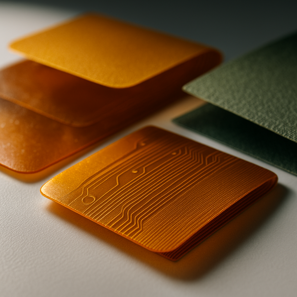
The foundation of every flexible PCB begins with substrate selection. Unlike rigid PCBs where FR-4 dominates, flexible circuits demand materials engineered specifically for repeated flexing, extreme temperatures, and diverse environmental conditions.
Polyimide (PI) stands as the industry workhorse for good reason. With operational temperatures reaching 260°C and exceptional dimensional stability, polyimide substrates power everything from automotive sensor arrays to medical imaging equipment. When FlexPlus manufactures flexible circuits for electric vehicle battery management systems, polyimide’s combination of thermal endurance and mechanical flexibility proves essential. The material maintains its dielectric properties across temperature extremes—critical when circuits flex repeatedly near heat-generating components.
Polyimide comes in two primary configurations: adhesive-based and adhesiveless. Adhesive-based constructions use acrylic or epoxy adhesives to bond copper to the substrate, offering cost advantages for standard applications. Adhesiveless polyimide, where copper is directly deposited onto the substrate, delivers superior thermal performance and thinner profiles—essential for applications like our 25-micron ultra-thin designs where every micron matters.
Polyester (PET) provides a cost-effective alternative for applications with less demanding requirements. With operational temperatures limited to approximately 105°C and lower flex life compared to polyimide, PET suits consumer electronics where cost optimization drives decisions. We’ve successfully manufactured PET-based circuits for consumer gadgets and display backlighting where the application involves static flexing during installation rather than dynamic bending during operation.
Liquid Crystal Polymer (LCP) represents the performance frontier. Its exceptionally low dielectric constant and low moisture absorption make LCP ideal for high-frequency applications like optical transceivers and RF modules. When telecommunications equipment manufacturers require precise signal integrity at multi-gigahertz frequencies, LCP’s electrical properties become non-negotiable. The material’s dimensional stability also shines in fine-pitch applications where trace spacing approaches 50 microns (2 mil).
Thermoplastic Polyurethane (TPU) circuits represent our breakthrough innovation for next-generation wearables and medical applications. TPU substrates offer a unique combination of biocompatibility, stretchability, and softness impossible with traditional materials. We’ve pioneered TPU circuit manufacturing for beauty tech gadgets and medical wearables where the circuit must conform to body contours while maintaining electrical performance. With substrate thickness ranging from 0.15mm to 1.0mm and copper foil options from 18 to 70 microns, TPU opens entirely new application possibilities.
Each substrate family brings distinct dielectric constants, thermal coefficients of expansion, and moisture absorption characteristics. For a medical device operating inside the human body, polyimide’s low moisture absorption (typically under 0.5%) prevents dimensional changes that could compromise reliability. For an automotive radar system, polyimide’s glass transition temperature above 250°C ensures the circuit maintains mechanical integrity during reflow soldering and operational thermal cycling.
Engineering Considerations: Matching Materials to Manufacturing and Application Realities
Theory meets reality when your design moves from CAD to production. The substrate you select determines not just electrical performance but manufacturability, cost structure, and long-term reliability.
Bend radius requirements often shock engineers accustomed to rigid PCBs. The minimum bend radius—typically specified as a multiple of total thickness—directly impacts where and how you can route flexible sections. For single-layer polyimide circuits, we can achieve bend radii as small as 6 times the total thickness. Multilayer constructions require more generous radii, typically 10 to 15 times thickness, to prevent copper cracking and delamination.
In our automotive harness projects extending up to 3 meters, we carefully map every bend location during design reviews. A sharp 90-degree corner that looks fine on screen becomes a reliability nightmare when the harness flexes during vehicle operation. We guide customers toward curved routing with generous radii—not as a manufacturing convenience but as engineering necessity for 15-year automotive lifetimes.
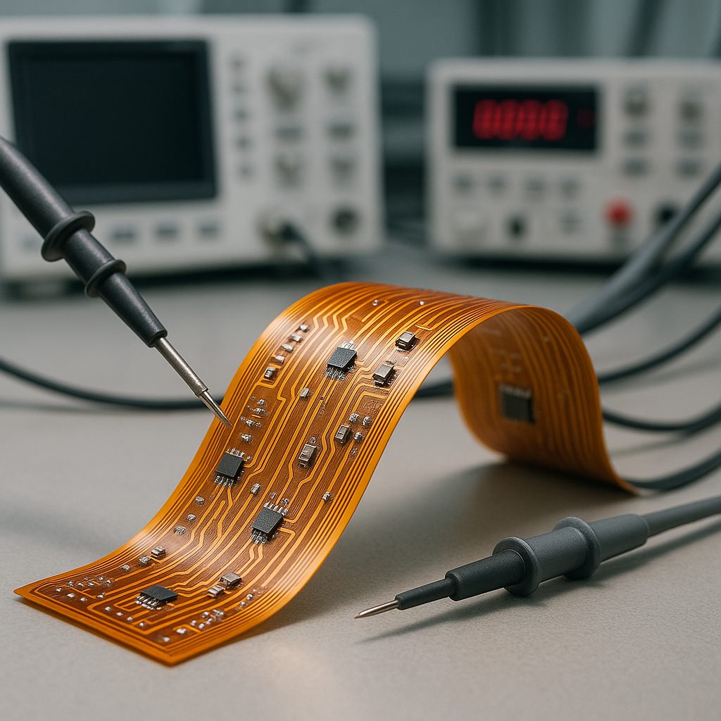
Dynamic versus static flexing fundamentally changes material requirements. A rigid-flex circuit that bends once during smartphone assembly faces entirely different stresses than a wearable device flexing thousands of times daily. For dynamic applications, adhesiveless polyimide with rolled-annealed copper delivers superior flex life. The absence of adhesive layers eliminates a potential failure mode, while rolled copper’s grain structure better accommodates repeated bending stress.
Coverlay versus solder mask decisions involve more than aesthetics. Coverlays—typically polyimide film bonded with adhesive—provide superior flexibility and tear resistance for circuits experiencing mechanical stress. Solder mask, while more cost-effective and suitable for fine-pitch pad exposure, sacrifices some flexibility. In our rigid-flex designs combining flexible interconnects with rigid component mounting areas, we strategically apply coverlay to flex regions and solder mask to rigid sections, optimizing both flexibility and manufacturability.
Copper weight selection requires balancing current-carrying capacity against flexibility. While 70-micron (2 oz) copper handles higher currents, it dramatically reduces flex life compared to 35-micron (1 oz) or 18-micron (0.5 oz) copper. For power delivery in automotive applications, we often specify heavier copper in rigid sections and transition to lighter copper in flex regions—maintaining current capacity while preserving bend performance where it matters most.
Material cost implications extend beyond substrate pricing. Polyimide costs more than polyester, but this price difference shrinks when you factor in yield rates and reliability. We’ve seen customers initially attracted to PET’s lower material cost later switch to polyimide after experiencing field failures from insufficient thermal performance. The true cost calculation must include prototype iterations, yield losses, and potential warranty expenses.
Thermal management integration increasingly influences material selection. Our proprietary flexible heat dissipation flow channel technology demonstrates how substrate choice enables innovative thermal solutions. For high-power LED applications and automotive power electronics, we engineer thermal pathways directly into flexible substrates, reducing operating temperatures while maintaining circuit flexibility. This approach proves impossible with certain substrate families, making thermal requirements a primary selection criterion rather than an afterthought.
Trace routing strategies adapt to material properties. In TPU circuits, we’ve developed specialized routing guidelines accounting for the substrate’s elasticity. Curved traces distribute stress more effectively than straight runs with corners. Cross-hatched ground planes, while standard in rigid PCBs, require careful analysis in flexible constructions where the hatching pattern affects mechanical properties.
For electromagnetic-sensitive applications like optical transceivers, material selection interacts with layer stack-up design. LCP’s low dielectric constant enables tighter impedance control, but only when combined with precise copper weight specification and careful ground plane design. We work with customers through Design for Manufacturing (DFM) analysis, evaluating how their trace routing, pad layouts, and via strategies interact with material properties before committing to production tooling. Our professional PCB design services ensure manufacturing-ready files that optimize both material performance and production efficiency.
Design Validation: Avoiding Common Material Selection Pitfalls
Every year, we receive design files from engineers who unknowingly specified material combinations that create manufacturing challenges or reliability risks. These common pitfalls cost weeks in redesign cycles and prototype iterations.
Pitfall 1: Ignoring coefficient of thermal expansion (CTE) mismatches. When rigid FR-4 sections bond to flexible polyimide sections in rigid-flex designs, the materials expand at different rates during thermal cycling. Without proper design compensation—such as strain relief features or strategic trace routing—this CTE mismatch generates mechanical stress causing failures after 500 to 1,000 thermal cycles. Our IATF 16949 certification for automotive applications includes extensive thermal cycling validation specifically addressing these concerns.
Pitfall 2: Specifying unrealistic layer counts for flex sections. While we manufacture flexible PCBs up to 8 layers, each additional layer reduces flexibility and increases minimum bend radius. Customers sometimes request 6-layer flex sections with tight bend radii physically impossible without risking copper cracking. During design reviews, we help optimize layer distribution—often placing signal layers in flex regions while concentrating power and ground planes in adjacent rigid sections.
Pitfall 3: Overlooking environmental certification requirements. Medical device manufacturers need ISO 13485-compliant processes and often require polyimide substrates meeting specific biocompatibility standards. Automotive customers require IATF 16949 certification and materials surviving automotive qualification testing. These certifications aren’t administrative details—they reflect validated material selections and manufacturing processes ensuring reliability. Discovering certification gaps after prototype success wastes months qualifying alternative materials.
Pitfall 4: Underestimating moisture sensitivity for specific applications. Polyester’s higher moisture absorption makes it unsuitable for outdoor automotive sensors or medical devices exposed to bodily fluids. We’ve guided customers away from PET when their application involves humidity exposure, even when initial testing showed acceptable performance. Long-term reliability requires material selection anticipating worst-case environmental conditions, not just nominal operating environments.
Pitfall 5: Neglecting minimum feature size limitations by material. LCP enables finer trace widths and spacing than standard polyimide due to superior dimensional stability. Specifying 50-micron (2 mil) traces on standard polyimide might push yield boundaries, while the same design on LCP processes routinely. Understanding how substrate choice affects minimum feature capability prevents disappointing prototype yields.
Your Material Selection Checklist: A Systematic Approach
Before finalizing your flexible PCB design, work through these critical evaluation points:
Application Environment Assessment:
- Operating temperature range (continuous and peak exposure)
- Flex cycles expected over product lifetime (static, occasional, or continuous flexing)
- Chemical exposure including cleaning agents, conformal coating compatibility
- Moisture and humidity conditions throughout service life
- Mechanical stress patterns beyond simple bending (twisting, compression)
Electrical Performance Requirements:
- Signal frequencies and impedance control needs
- Dielectric constant and loss tangent at operating frequencies
- Current carrying requirements by circuit section
- EMI/EMC shielding requirements
Manufacturing and Cost Considerations:
- Production volume (prototype, pilot, or mass production)
- Required turnaround time (standard or emergency)
- Assembly complexity (SMT components, connector types, stiffener requirements)
- Quality certifications needed (ISO 13485, IATF 16949, UL)
Reliability and Testing:
- Expected product lifetime and warranty requirements
- Qualification testing standards applicable to your industry
- Field failure consequences and acceptable risk levels
For complex applications combining multiple requirements, material selection becomes an optimization problem rather than a simple lookup. Our engineering team regularly conducts joint development projects where we test multiple substrate options, validate designs through accelerated life testing, and iterate toward the optimal solution balancing performance, manufacturability, and cost.
From Material Selection to Manufacturing Excellence
Material selection represents just one element in successful flexible PCB development, but it’s a decision that influences every downstream choice. The polyimide you specify determines thermal process windows during assembly. The copper weight affects via reliability in multilayer stack-ups. The coverlay adhesive impacts final thickness and flexibility.
At FlexPlus, our 20+ years specializing in flexible and rigid-flex manufacturing means we’ve navigated these trade-offs across applications from 25-micron medical wearables to 4-meter automotive harnesses. Our comprehensive certifications—ISO 9001, ISO 13485, IATF 16949, and ISO 14001—reflect validated processes ensuring consistent quality regardless of your chosen materials.
We’ve pioneered breakthrough technologies like TPU circuits and flexible heat dissipation channels because we understand that material innovation drives application possibilities. When standard substrates can’t meet your requirements, our R&D capabilities and full in-house manufacturing control enable us to develop customized solutions.
Most importantly, we approach material selection as an engineering partnership. Through DFM analysis, we evaluate your designs against 20 years of manufacturing experience, identifying potential issues before you invest in tooling. Our direct communication with production engineers—impossible when working through brokers—means you receive specific, actionable feedback on how material choices impact manufacturability, yield, and reliability.
Whether you’re developing your first flexible PCB or optimizing an existing design for mass production, material selection deserves thorough analysis guided by manufacturing expertise. The substrate you choose today determines whether your product succeeds in field trials or becomes another cautionary tale of overlooked engineering fundamentals.
Your next flexible PCB begins with the right material conversation. Connect with FlexPlus to discuss how our certified manufacturing capabilities and material expertise can transform your innovative designs into reliable, production-ready solutions. Because in flexible PCB manufacturing, excellence starts with engineering the right foundation—one substrate at a time.