
When a drone loses power mid-flight or experiences sudden control failure, the consequences extend beyond a crashed aircraft. For commercial delivery drones, it means lost cargo and damaged reputation. For agricultural survey drones, it represents incomplete data and wasted operational costs. For emergency response UAVs, it could mean the difference between a successful rescue and a tragedy.
The root cause of these failures often traces back to a single source: inadequate PCB design specifications. Unlike consumer electronics that operate in controlled environments, drone circuit boards face extreme mechanical stress, temperature fluctuations, and electromagnetic interference—all while maintaining critical flight control systems. A single thermal hotspot or electromagnetic disturbance can cascade into complete system failure at the worst possible moment.
This article examines the essential PCB design specifications for drone applications that separate reliable drone electronics from potential mid-flight failures, drawing from over two decades of manufacturing experience serving the aerospace and UAV industries.
Building the Foundation: Technical Specifications for Drone PCBs
The physical characteristics of a drone PCB directly impact both flight performance and system reliability. Every milligram matters when your circuit board determines flight time, and every millimeter of thickness affects the drone’s center of gravity.
Copper weight selection requires balancing current-carrying capacity against overall mass. While 35μm (1 oz) copper suffices for signal traces, power distribution paths demand 70μm (2 oz) copper to handle the high currents drawn by electronic speed controllers (ESCs) and flight control processors. This specification isn’t arbitrary—insufficient copper weight creates resistance hotspots that degrade under thermal cycling, eventually leading to open circuits during flight.
Consider a commercial delivery drone drawing 30 amperes through its power distribution network. With 35μm copper, a 2mm-wide trace generates approximately 0.8 watts of heat per centimeter. Over a 10cm power path, that’s 8 watts of unnecessary thermal load. Upgrading to 70μm copper cuts this heating by half, extending component lifespan and preventing thermal-induced failures during high-demand flight maneuvers.
Board thickness presents a delicate optimization challenge. Thicker boards (1.6mm) provide mechanical rigidity that resists vibration-induced flexing, but add unnecessary weight. Ultra-thin designs (0.4mm) minimize mass but risk mechanical damage during assembly and operation. The optimal specification typically ranges from 0.8mm to 1.2mm, providing structural integrity without excessive weight penalty.
For rigid-flex configurations—increasingly common in folding-arm drone designs—the transition zones between rigid and flexible sections require careful engineering. Our experience manufacturing rigid-flex boards up to 12 layers has shown that gradual thickness transitions reduce stress concentration points by up to 60%, dramatically lowering the risk of delamination during repeated folding cycles.
Layer stackup strategy must account for signal integrity, power delivery, and mechanical constraints simultaneously. A typical 6-layer drone flight controller stackup might allocate:
– Top layer: High-speed signal routing (IMU, GPS, telemetry)
– Inner layer 1: Ground plane (continuous reference)
– Inner layer 2: Power distribution (+5V, +3.3V)
– Inner layer 3: Power distribution (battery voltage, motor power)
– Inner layer 4: Ground plane (shielding)
– Bottom layer: Component placement and signal routing
This arrangement provides dual ground planes for electromagnetic shielding while dedicating two full layers to power distribution. The continuous ground planes reduce return path impedance for high-frequency signals—critical when your flight controller processes IMU data at kilohertz rates.
Thermal Management: Keeping Cool Under Pressure
Drone electronics generate substantial heat in a compact volume with limited natural convection. A flight controller running sensor fusion algorithms while managing multiple communication protocols can easily exceed 70°C junction temperature without proper thermal design. Add in the heat from voltage regulators stepping down battery voltage, and you have a thermal management crisis waiting to happen.
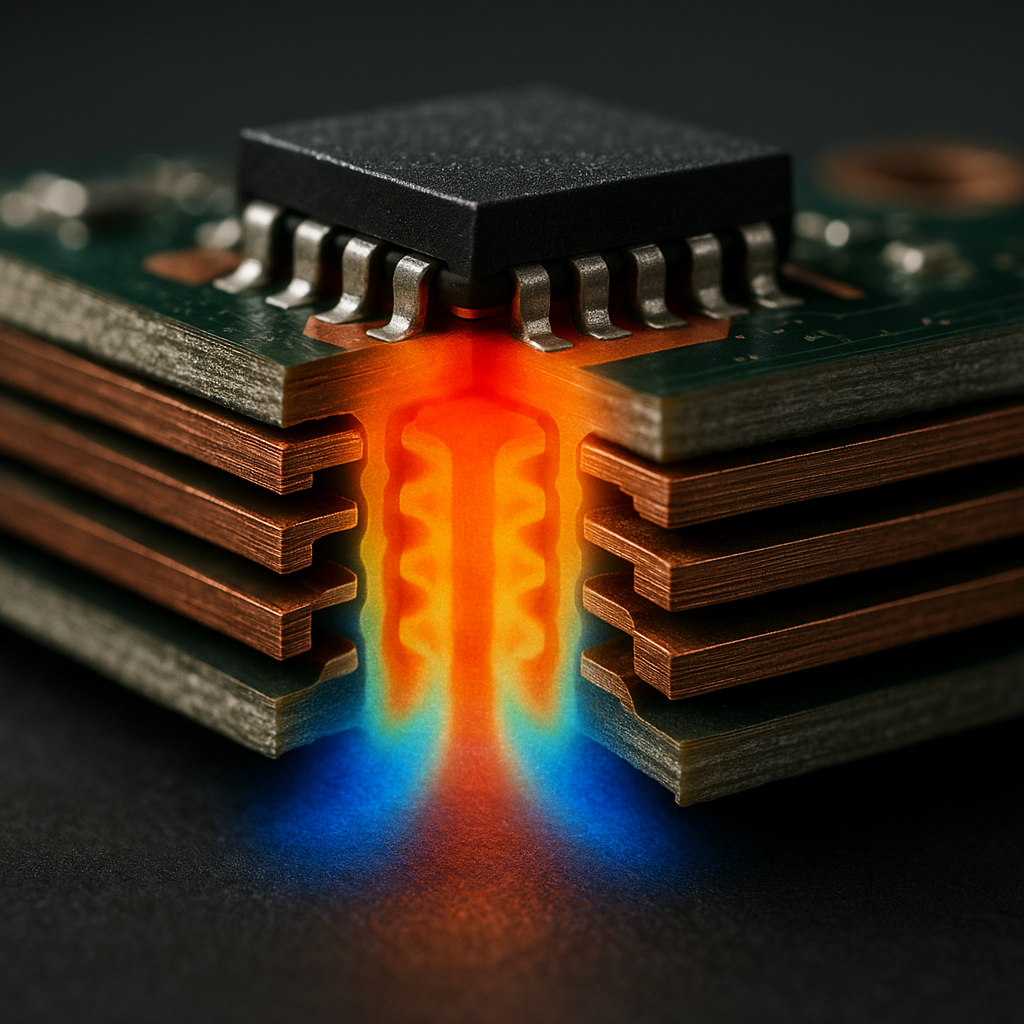
Thermal vias form the primary heat extraction pathway in modern drone PCBs. These copper-plated holes conduct heat from surface-mounted components through the board layers to larger copper areas or heatsinks. The specifications matter enormously: 0.3mm diameter vias with 0.6mm spacing create an effective thermal highway with minimal board real estate consumption.
For a high-power voltage regulator dissipating 3 watts in a compact QFN package, a thermal via array beneath the thermal pad can reduce junction-to-ambient thermal resistance by 40%. This translates directly to lower operating temperatures and exponentially longer component lifespan. The relationship is quantifiable—every 10°C reduction in operating temperature roughly doubles semiconductor life expectancy.
Copper pour strategies extend beyond simple ground planes to create thermal mass distribution. Wide copper areas on outer layers act as passive heatsinks, spreading localized heat across larger surface areas. For boards operating in sealed enclosures—common in weatherproofed drones—this thermal spreading becomes the primary cooling mechanism.
One practical implementation places a solid copper pour connected to the ground plane beneath and around power-hungry components like the main processor and ESC interface circuits. This 2mm-wide copper border, implemented using the flexible circuit manufacturing capabilities that can accommodate up to 70μm copper thickness, provides both electromagnetic shielding and thermal conduction pathways.
Active cooling integration becomes necessary for high-performance applications. Mounting provisions for miniature heatsinks must be designed into the PCB layout from the start, with appropriate keepout zones ensuring adequate airflow. For drones with brushless cooling fans, the PCB must accommodate fan connectors while maintaining proper component spacing to prevent airflow blockages.
The challenge intensifies in compact racing drones or industrial inspection UAVs where space constraints limit heatsink size. Here, thermal design optimization makes the difference between reliable operation and thermal shutdown during critical missions.
Electromagnetic Compatibility: Preventing Invisible Interference
Electromagnetic interference represents one of the most insidious failure modes in drone electronics. Unlike mechanical failures that produce obvious symptoms, EMI-induced malfunctions manifest as subtle GPS position drift, compass heading errors, or occasional radio control glitches—exactly the kind of intermittent problems that cause mid-flight failures.
Shielding strategies begin with proper ground plane design. A continuous ground plane beneath high-frequency digital circuits provides a low-impedance return path and acts as an electromagnetic barrier between circuit layers. Breaking this ground plane—even for a seemingly innocent trace route—can increase radiated emissions by 10-20 dB at critical frequencies.
For drone applications with onboard FPV video transmitters or long-range telemetry modules, additional shielding becomes mandatory. Metal RF shields over the flight controller or GPS module prevent transmitted RF energy from coupling into sensitive analog circuits. The PCB design must accommodate these shields with appropriate grounding connections, typically achieved through perimeter ground vias spaced no more than 3mm apart—roughly one-tenth wavelength at 1 GHz.
Layout techniques play an equally critical role. Segregating the board into functional zones—power conditioning, flight control processor, radio modules, motor drivers—prevents crosstalk between subsystems. Physical separation by just 5-10mm, combined with ground plane partitioning, can reduce inter-system interference by orders of magnitude.
Clock signal routing demands special attention. A 72 MHz microcontroller clock has harmonic content extending into the UHF spectrum, potentially interfering with GPS reception or 5.8 GHz video links. Proper routing keeps clock traces short, implements series termination resistors, and avoids parallel routing near sensitive RF circuits.
Filtering implementation provides the final defense against conducted emissions. Every power input should incorporate LC filter stages, with ferrite beads suppressing high-frequency noise while bulk capacitors handle low-frequency transients. For a typical drone flight controller receiving power from a switching battery eliminator circuit (BEC), a three-stage filter—ferrite bead, 10μF ceramic capacitor, and 100μF electrolytic capacitor—effectively attenuates switching noise across the entire frequency spectrum.
The electromagnetic environment inside a drone is particularly hostile. Brushless motors generate massive EMI through their switching action, with rise times measured in nanoseconds. ESCs operating at 20-40 kHz switching frequencies create both conducted and radiated noise. Without proper filtering and shielding, this electrical chaos overwhelms sensitive sensors and corrupts communication signals.
Connectors and Cabling: The Weak Links
Connectors represent the highest failure rate component in drone electronics, subjected to repeated vibration, thermal cycling, and mechanical stress. Yet they’re often an afterthought in PCB design, selected based on availability rather than reliability requirements.
Connector selection for drone applications demands rugged, vibration-resistant designs with positive locking mechanisms. Standard pin headers have no place in serious UAV designs—they work loose under vibration within hours of operation. Proper drone connectors feature locking tabs, polarization keys, and contact retention systems that maintain electrical connection under 10G shock loads.
For power distribution, high-current connectors must provide low contact resistance to minimize voltage drop and heating. A connector rated for 30 amperes continuous with 10 milliohm contact resistance generates 9 watts of heat at full load—more than many voltage regulators. Upgrading to a connector with 3 milliohm contacts reduces this heating by 70%, preventing thermal degradation of the connector housing and solder joints.
PCB mounting considerations extend beyond simple through-hole soldering. Connectors experiencing repeated mating cycles or carrying mechanical loads require additional support. Through-hole mounting posts that engage the PCB on multiple layers distribute stress across a larger area, preventing pad liftoff and barrel fractures. For critical connectors, we recommend specifying edge-mounting configurations that transfer mechanical loads directly to the PCB edge rather than solder pads.
EMI shielding in cabling often receives insufficient attention during design. Unshielded wires carrying high-frequency signals act as antennas, radiating emissions and picking up interference. For connections between the flight controller and ESCs, GPS modules, or telemetry radios, shielded cables with proper 360-degree termination at both ends provide 20-30 dB EMI suppression.
The connector footprint design itself impacts reliability. Oversized pads with thermal relief spokes ease hand-soldering but compromise mechanical strength. For volume production using automated assembly—the standard approach for manufacturing flexible PCBs at scale—the pad geometry must balance solderability with mechanical retention strength. Properly designed connector footprints withstand 20 Newtons of pull force without pad separation.
Manufacturing Practicality and Testing
The most sophisticated PCB design means nothing if it cannot be manufactured reliably at scale. Design for manufacturability (DFM) principles separate theoretical PCB designs from production-ready specifications that deliver consistent quality across thousands of units.
Producibility constraints begin with minimum feature sizes. While 0.05mm trace width and spacing represents our advanced manufacturing capability, drone PCBs benefit from relaxing these specifications to 0.1mm where possible. This tolerance margin dramatically improves manufacturing yield, reduces defect rates, and lowers production costs—critical factors for commercial drone manufacturers facing competitive pricing pressure.
Component placement density requires similar pragmatism. Dense component packing minimizes board size and weight, but complicates automated assembly and inspection. Maintaining minimum 0.5mm spacing between components enables reliable optical inspection and reduces solder bridge defects. For components generating heat, increasing spacing to 1-2mm improves thermal performance while simplifying assembly.
Testing methodologies must verify both electrical performance and mechanical integrity. Standard electrical testing—continuity checks, insulation resistance measurement, and high-potential testing—ensures basic circuit functionality. However, drone applications demand additional verification steps.
Flying probe testing or bed-of-nails fixtures verify individual nets without relying on component loading, catching manufacturing defects before costly assembly operations. For flexible and rigid-flex boards used in folding-arm drones, dynamic flexure testing validates the design survives repeated folding cycles without conductor fracture or delamination.
Environmental stress screening simulates real-world operating conditions. Temperature cycling between -40°C and +85°C while monitoring electrical parameters reveals latent defects in solder joints, component attachment, and layer adhesion. Vibration testing at frequencies matching drone rotor harmonics (typically 50-200 Hz) identifies mechanical resonance issues before field deployment.
Quality standards compliance provides assurance that manufacturing processes meet aerospace requirements. Our ISO 9001, IATF 16949, and ISO 13485 certifications reflect systematic quality management applicable to drone applications spanning commercial, industrial, and medical sectors. These standards mandate documented processes for design validation, production control, and traceability—essential for drone manufacturers requiring consistent quality across production batches.
Best Practices and Common Pitfalls
Twenty years of manufacturing flexible PCBs for demanding applications has revealed recurring design patterns that either enhance or compromise reliability.
Best practices include:
– Specifying 1.2mm board thickness for rigid sections, transitioning to 0.2-0.4mm flexible sections in rigid-flex designs
– Implementing dual ground planes in 6+ layer stackups for superior EMI shielding
– Placing high-frequency crystals and oscillators within 10mm of their associated processors
– Using 0.3mm thermal vias in 0.6mm grid patterns beneath power components
– Designing connector footprints with 3mm minimum edge clearance for mechanical stress relief
Common pitfalls to avoid:
– Routing high-speed signals across split ground planes, creating return path discontinuities
– Omitting series termination on clock lines, generating excessive EMI
– Specifying inadequate copper weight for power distribution paths, causing thermal hotspots
– Neglecting thermal via arrays beneath QFN packages, leading to overheating failures
– Placing sensitive analog circuits adjacent to switching power supplies without isolation
Quick-start checklist for drone PCB designers:
1. Calculate trace widths for maximum operating current plus 50% margin
2. Verify continuous ground plane coverage beneath all high-frequency circuits
3. Implement LC filtering on all power inputs with 10μF + 100μF capacitor pairs
4. Specify locking connectors for all external interfaces
5. Design thermal via arrays using 0.3mm vias at 0.6mm pitch beneath power components
6. Maintain 5mm minimum separation between RF circuits and digital processors
7. Route high-speed differential pairs with matched lengths within 0.5mm
8. Specify conformal coating for environmental protection in production documentation
Conclusion
Preventing mid-flight failures in drone applications demands rigorous attention to PCB design specifications across multiple domains. The copper weight, board thickness, and layer stackup form the foundation for reliable operation. Thermal management through vias, copper pours, and heat dissipation paths maintains component temperatures within safe operating limits. EMI shielding and proper layout techniques ensure electromagnetic compatibility in the hostile electrical environment inside a UAV. Rugged connectors and appropriate cabling preserve signal integrity while withstanding mechanical stress. Finally, manufacturing practicality and comprehensive testing validate that designs translate into reliable production hardware.
The difference between a drone that completes its mission and one that fails catastrophically often comes down to these fundamental specifications. For engineers developing commercial UAVs, agricultural survey platforms, or industrial inspection drones, investing engineering effort in proper PCB design yields exponential returns in reliability and operational safety.
With comprehensive design support, advanced manufacturing capabilities spanning from prototyping to volume production, and two decades of experience serving the aerospace industry, FlexPlus stands ready to transform your drone PCB designs into flight-ready hardware that performs reliably mission after mission.