
When engineers at an electric vehicle manufacturer discovered that their flexible circuit assemblies were failing during temperature cycling tests, the root cause wasn’t a design flaw—it was material selection. The substrate couldn’t handle repeated thermal expansion and contraction. This single material choice cascaded into months of redesign work and delayed production timelines.
This scenario plays out more often than you’d think. In flexible PCB manufacturing, material selection determines whether your circuit thrives in demanding applications or fails in the field. After working with over 2,500 customers across aerospace, medical devices, and automotive electronics over the past 20 years, we’ve learned that understanding flex PCB materials isn’t just technical knowledge—it’s the foundation of reliable product performance.
The Critical Role of Substrate Materials
The substrate forms the backbone of every flexible circuit. Think of it as the stage where all electrical performance happens. Choose the wrong substrate, and even perfect circuit design won’t save your application.
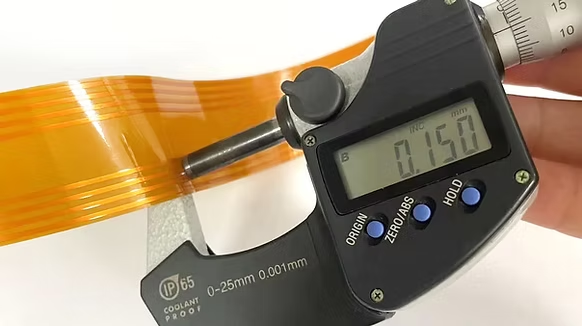
Polyimide stands as the primary substrate material for professional flex PCB applications, and for good reason. This amber-colored film withstands continuous operating temperatures up to 200°C and can handle thermal spikes beyond 400°C during assembly processes like reflow soldering. When a medical device manufacturer needed flexible circuits for implantable sensors that would undergo multiple sterilization cycles at 134°C, only polyimide could deliver the required thermal stability combined with biocompatibility.
Beyond temperature resistance, polyimide offers exceptional mechanical properties. Its elongation capability—typically 40% to 70%—means the material can flex repeatedly without developing microcracks that compromise circuit integrity. In dynamic applications like robotic arms or automotive door modules where circuits bend thousands of times, this flexibility translates directly to product longevity. Engineering data from our manufacturing floor shows that properly designed polyimide circuits routinely survive 100,000+ flex cycles in accelerated life testing.
Polyimide also brings dimensional stability to the table. Unlike materials that shrink or expand significantly with temperature changes, polyimide maintains tight tolerances. This stability matters immensely for high-density interconnect designs where trace spacing reaches 0.05mm. When tolerances slip, circuits short or fail—polyimide keeps everything aligned.
For applications where cost constraints outweigh thermal demands, polyester (PET) offers an alternative. At roughly one-third the cost of polyimide, polyester works well in consumer electronics that never exceed 105°C operating temperature. We’ve seen it successfully deployed in simple membrane switches and low-cost LED applications. However, polyester lacks polyimide’s chemical resistance and dimensional stability. One consumer electronics client learned this the hard way when their polyester-based circuits warped during assembly, requiring a costly material switch to polyimide mid-production.
The choice between polyimide and polyester isn’t about which material is “better”—it’s about matching material properties to your application requirements. High-reliability applications in automotive, aerospace, or medical devices demand polyimide. Cost-sensitive, low-temperature consumer applications can leverage polyester’s economic advantages.
Conductive Materials: The Highway for Electrical Signals
Copper thickness and processing method directly impact your flexible circuit’s electrical performance and mechanical behavior. The copper foil choice might seem technical, but it determines whether your circuit performs reliably or develops fatigue cracks after repeated bending.
Rolled-annealed copper represents the premium choice for dynamic flex applications. The rolling process creates a uniform grain structure with superior ductility compared to electrodeposited alternatives. When a flexible circuit bends, rolled-annealed copper’s grain structure allows the material to stretch without developing the microcracks that eventually cause electrical failures. Think of it like the difference between a woven fabric that flexes easily versus a rigid sheet that eventually tears—rolled-annealed copper’s internal structure is optimized for movement.
This material choice becomes critical in applications like smartphone hinge assemblies or laptop display cables where circuits flex every time the device opens and closes. Our testing data shows rolled-annealed copper circuits consistently outlast electrodeposited alternatives by 300% in dynamic flex testing. For a tablet manufacturer, switching from electrodeposited to rolled-annealed copper eliminated field failures in their hinge assemblies—failures that had been plaguing warranty returns.
Rolled-annealed copper also delivers smoother surface characteristics. Surface roughness affects signal integrity, particularly at higher frequencies. In telecommunications applications like optical transceivers where signal quality is paramount, the smoother copper surface reduces signal loss and maintains better impedance control across the circuit length.
Electrodeposited copper serves static applications effectively at lower cost. When a circuit mounts permanently in an enclosure with minimal flexing, the superior ductility of rolled-annealed copper becomes unnecessary. Industrial control panels, stationary sensor assemblies, and many consumer electronics use electrodeposited copper successfully. The key is honest assessment—if your application involves repeated flexing, invest in rolled-annealed copper. If the circuit remains static after installation, electrodeposited copper delivers adequate performance at reduced cost.
Copper weight selection—typically ranging from 18μm (½ oz) to 70μm (2 oz)—balances current-carrying capacity against flexibility. Thicker copper handles higher currents but reduces flexibility and increases minimum bend radius requirements. For high-current automotive applications like battery management systems, 35μm or 70μm copper might be necessary. For sensitive medical implant sensors, ultra-thin 18μm copper maximizes flexibility while meeting current requirements.
Adhesives and Coverlay: The Protective Shield
Protection layers determine whether environmental factors degrade your flexible circuit or whether it maintains performance throughout its service life. These materials also contribute significantly to overall circuit reliability under mechanical stress.
Traditional flexible circuits use adhesive systems to bond copper to substrate and apply protective coverlays. Acrylic adhesives dominate the industry due to their balance of properties and processing ease. However, adhesive selection impacts both thermal performance and mechanical behavior. Adhesive layers add thickness, reduce overall flexibility, and create potential failure points under extreme conditions.
Some high-reliability applications demand adhesiveless construction where copper bonds directly to polyimide without intermediate adhesive layers. This construction method, while more expensive, delivers superior thermal performance and thinner overall construction. When an aerospace client needed flexible circuits for aircraft engine monitoring—an environment combining high temperatures with severe vibration—only adhesiveless construction could meet their reliability requirements.
Coverlay serves as the protective outer layer, shielding copper traces from environmental damage, mechanical abrasion, and electrical shorting. Like the substrate, coverlay typically uses polyimide film with an adhesive layer. The coverlay selection must complement the base substrate—mixing polyimide substrate with polyester coverlay, for example, creates thermal expansion mismatches that lead to delamination under temperature cycling.
Coverlay thickness affects overall circuit flexibility. Thinner coverlay (typically 12.5μm polyimide plus 12.5μm adhesive) maximizes flexibility but provides less mechanical protection. Thicker coverlay (25μm polyimide plus 25μm adhesive) offers superior environmental protection but reduces overall flexibility. The choice depends on your application environment—circuits destined for harsh industrial environments need the protection of thicker coverlay, while miniaturized wearable devices demand maximum flexibility with thinner coverlay.
An alternative approach uses soldermask instead of coverlay. Liquid photoimageable soldermask—similar to what’s used on rigid PCBs—can protect flexible circuits at reduced cost and thickness. However, soldermask lacks coverlay’s mechanical strength and flex life performance. We recommend soldermask for static flex applications or areas of dynamic circuits that don’t undergo repeated flexing. For truly dynamic regions, coverlay remains the superior choice.
The aperture design in coverlay—the openings for component pads and connectors—requires careful planning. Sharp corners in coverlay apertures create stress concentration points where cracks can initiate during flexing. Our design guidelines recommend minimum 0.5mm radius curves at all coverlay aperture corners to distribute stress and prevent stress-related failures.
Stiffeners: Strategic Reinforcement
Flexible circuits often require rigid sections for component mounting, connector attachment, or additional mechanical support. These stiffener materials transform specific areas of the flexible circuit into rigid zones while maintaining flexibility elsewhere.
Polyimide stiffeners offer the most common solution, bonded to the flexible circuit using pressure-sensitive adhesive (PSA) or thermally activated adhesive film. Stiffener thickness typically ranges from 0.1mm to 0.5mm depending on required rigidity. For component mounting areas, thicker stiffeners provide the dimensional stability needed during assembly processes. When SMT components mount to flexible circuits, the rigid stiffener area prevents the flexible substrate from warping under the heat and pressure of reflow soldering.
Stainless steel stiffeners deliver superior rigidity in connector areas. When a flex circuit mates with a ZIF (Zero Insertion Force) connector, the insertion forces can damage unprotected flexible circuits. Metal stiffeners provide the mechanical strength to withstand repeated connector insertions without tearing or deforming the circuit. An automotive client using flex circuits in their dashboard assemblies found that stainless steel stiffeners at connector interfaces completely eliminated the connector damage they’d experienced with polyimide stiffeners.
FR-4 stiffeners serve dual purposes—providing rigidity while also offering the routing capabilities of traditional rigid PCBs. In rigid-flex constructions, FR-4 sections can host complex component assemblies while flexible sections provide interconnections. This combination reduces overall system complexity by eliminating connectors and cables while maintaining the benefits of both rigid and flexible circuit technologies.
Stiffener placement requires strategic thinking. Over-stiffening a flexible circuit defeats its purpose, while under-stiffening leaves vulnerable areas unprotected. Our engineering team works with clients to identify critical reinforcement zones—typically component mounting areas, connector interfaces, and mounting points—while preserving flexibility in interconnection regions.
Surface Finishes: The Final Layer
Surface finish selection impacts both immediate solderability and long-term reliability. The finish protects exposed copper pads from oxidation while providing a solderable surface for component attachment.
Electroless Nickel Immersion Gold (ENIG) stands as the industry standard for high-reliability flexible circuits. The nickel barrier layer prevents copper migration, while the gold surface provides excellent solderability and wire bonding compatibility. ENIG’s flat, uniform surface makes it ideal for fine-pitch components. Medical device manufacturers consistently specify ENIG because it handles multiple thermal cycles during assembly and sterilization without degrading solderability.
However, ENIG introduces mechanical considerations for flexible circuits. The nickel layer is inherently brittle—circuits with ENIG finish in dynamic flex areas can develop cracks in the nickel layer under repeated flexing. These cracks don’t immediately cause failure but can propagate over time, eventually compromising circuit reliability. For this reason, we recommend restricting ENIG to static areas of flexible circuits or considering alternative finishes for highly dynamic applications.
Immersion Silver offers excellent solderability at lower cost than ENIG while maintaining better flexibility. The thin silver layer doesn’t create the brittleness concerns of nickel. For applications where wire bonding isn’t required, immersion silver delivers reliable performance. The downside? Silver tarnishes over time when exposed to sulfur-containing environments, potentially compromising long-term solderability. Proper storage in sealed, moisture-controlled environments mitigates this concern.
Electroless Nickel Electroless Palladium Immersion Gold (ENEPIG) represents the premium finish choice for applications requiring both excellent solderability and wire bonding capability. The palladium layer between nickel and gold prevents the corrosion issues that occasionally plague ENIG. ENEPIG serves critical applications in aerospace and medical devices where absolute reliability justifies the additional cost.
Hot Air Solder Leveling (HASL) rarely appears on professional flexible circuits. The high processing temperatures (typically 260°C) risk damaging polyimide substrates, and the thick, uneven finish creates problems for fine-pitch components. We steer clients away from HASL unless specific legacy requirements demand it.
Understanding Material Properties and Performance
Material selection ultimately comes down to understanding how mechanical and thermal properties translate to real-world performance. Engineering teams need to evaluate several key parameters when specifying flexible circuit materials.
Glass transition temperature (Tg) indicates when a material transitions from rigid to rubbery behavior. Polyimide’s Tg exceeds 360°C, meaning it maintains dimensional stability through all normal assembly processes. Materials with lower Tg values soften during reflow soldering, causing dimensional changes that can misalign fine-pitch features.
Coefficient of thermal expansion (CTE) describes how much a material expands per degree of temperature change. Mismatched CTE values between layers create internal stresses during temperature cycling. When polyimide substrate (CTE around 20 ppm/°C) bonds to copper (CTE around 17 ppm/°C), the relatively close values minimize stress. Introducing materials with widely different CTE values—like certain adhesives with CTE above 50 ppm/°C—creates stress that can cause delamination during temperature cycling.
Dielectric constant and dissipation factor matter for high-frequency applications. Polyimide’s consistent dielectric properties across a wide frequency range make it suitable for RF flexible circuits in telecommunications equipment. When signal integrity is critical, material selection must consider these electrical properties alongside mechanical requirements.
Moisture absorption affects both electrical and mechanical properties. Polyimide absorbs minimal moisture (typically less than 3% by weight), maintaining stable properties across varying humidity conditions. Materials with high moisture absorption can experience dimension changes, reduced dielectric strength, and compromised adhesion—all reliability concerns in deployed products.
Engineering Partnership for Material Success
Selecting the right materials for your flexible circuit application requires balancing numerous competing requirements—thermal performance, flexibility, cost, manufacturability, and reliability. At FlexPlus, our 20+ years of specialized experience manufacturing flexible and rigid-flex circuits across diverse industries gives us unique insight into these trade-offs.
We’ve earned ISO 9001, ISO 13485, IATF 16949, and ISO 14001 certifications not just to check boxes, but to demonstrate our commitment to systematic quality throughout material selection, manufacturing processes, and final inspection. These certifications reflect mature processes refined over thousands of customer projects.
Our engineering team provides Design for Manufacturing (DFM) support that evaluates material choices against your application requirements. We identify potential issues before production begins—whether it’s a substrate thickness that won’t survive your required bend radius, a copper weight inadequate for your current requirements, or a surface finish inappropriate for your assembly process. This early collaboration eliminates costly redesigns and production delays.
When you partner with FlexPlus, you’re not just buying flexible circuits—you’re accessing two decades of material expertise applied to your specific challenges. We’ve solved material selection puzzles for electric vehicle battery management systems, medical implant sensors, aerospace avionics, industrial control systems, and cutting-edge consumer electronics. That breadth of experience informs every material recommendation we make.
Material selection represents the foundation of reliable flexible circuit performance. Whether you’re designing dynamic flex circuits for robotic applications, high-reliability rigid-flex assemblies for medical devices, or cost-optimized flexible circuits for consumer electronics, the material choices you make today determine your product’s performance tomorrow. Choose wisely, choose materials optimized for your specific application, and partner with manufacturers who bring deep expertise to guide these critical decisions.