
In today’s rapidly evolving electronics landscape, engineers face an increasingly complex challenge: designing circuits that must fit into tight spaces, withstand constant movement, and deliver reliable performance over extended periods. Rigid-Flex PCBs have emerged as the answer to this challenge, combining the structural stability of traditional rigid boards with the adaptability of flexible circuits. These hybrid marvels have become indispensable in industries ranging from electric vehicles and medical devices to aerospace systems and consumer electronics. Yet, beneath their sophisticated design lies a fundamental truth—the materials you choose today will determine whether your product thrives or fails tomorrow.
The lifespan of a Rigid-Flex PCB isn’t just about manufacturing quality or design cleverness. It’s fundamentally about the materials that form its foundation. Every polyimide layer, every copper trace, and every bonding method contributes to how your circuit will perform under stress, temperature fluctuations, and the relentless demands of real-world applications. As Flex Plus (Xiamen) Co., Ltd has discovered through two decades of manufacturing experience, understanding this relationship between material selection and product longevity isn’t optional—it’s essential for success.
The Anatomy of a Hybrid Solution
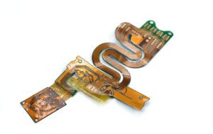
To appreciate why material choice matters so profoundly, we first need to understand what makes Rigid-Flex PCBs unique. Unlike their purely rigid or flexible counterparts, these boards exist in a carefully orchestrated balance between two worlds.
At their core, Rigid-Flex PCBs consist of multiple conductive layers—typically copper traces ranging from 18 to 70 micrometers in thickness—separated by insulating materials. The flexible portions usually employ polyimide as the substrate material, chosen for its exceptional ability to bend repeatedly without fracturing. Meanwhile, the rigid sections often utilize FR4 or other glass-reinforced epoxy laminates that provide the structural support necessary for mounting components and maintaining dimensional stability.
The stackup configuration of a Rigid-Flex PCB resembles a carefully constructed sandwich. Conductive layers alternate with insulating materials, with transition zones where rigid and flexible sections meet representing critical areas that require special attention. These transition zones must smoothly transfer electrical signals while accommodating mechanical stress—a challenge that demands precise material matching and expert engineering.
What makes Rigid-Flex PCBs particularly valuable is their ability to eliminate traditional connectors and cables. Consider a smartphone camera module: instead of using separate rigid boards connected by fragile flex cables, a single Rigid-Flex PCB can fold around tight spaces, directly connecting the image sensor to the main board while supporting surface-mount components. This integration reduces failure points dramatically—studies show that up to 75% of electronic failures occur at connection points. By eliminating these vulnerable junctions, Rigid-Flex designs inherently improve reliability.
The flexible substrates enable complex three-dimensional geometries that would be impossible with rigid boards alone. Medical devices like endoscopic cameras exploit this capability, threading sophisticated electronics through spaces measured in millimeters. Aerospace applications leverage the weight reduction—Rigid-Flex PCBs can be up to 75% lighter than equivalent rigid board assemblies with cables—while maintaining the ruggedness required for extreme environments.
Material Selection: The Foundation of Longevity
If design determines what a Rigid-Flex PCB can do, materials determine how long it will do it. The difference between a circuit that lasts five years and one that endures twenty often comes down to choices made at the material specification stage.
Traditional flexible PCBs have historically relied on adhesive-based laminates, where copper foil is bonded to the polyimide substrate using acrylic or epoxy adhesives. While functional, these adhesive layers introduce inherent limitations. They typically possess lower temperature resistance—often maxing out around 105°C—which restricts their use in high-heat environments like automotive under-hood applications or industrial control systems. More problematically, adhesives can degrade over time, particularly when exposed to thermal cycling, where components repeatedly heat and cool during operation.
Adhesiveless laminates represent a significant advancement in Rigid-Flex PCB technology. In these materials, copper is directly bonded to the polyimide substrate through a chemical or thermal process, eliminating the adhesive layer entirely. The benefits are substantial and measurable. Without the adhesive layer, these laminates demonstrate superior dimensional stability—critical when maintaining precise alignment across multiple layers in high-density interconnect designs. Thermal performance improves dramatically, with some adhesiveless constructions withstanding continuous operating temperatures exceeding 200°C.
The electrical advantages of adhesiveless laminates shouldn’t be overlooked either. Adhesive layers typically have higher dielectric constants and loss tangents than polyimide, meaning they degrade signal integrity—particularly problematic in high-frequency applications like telecommunications equipment or radar systems. By removing this lossy material, adhesiveless constructions reduce signal attenuation and improve impedance control, extending the reliable operating life of high-speed circuits.
For the rigid sections, material selection equally impacts longevity. High-temperature FR4 prepregs—the glass-reinforced epoxy sheets used to build up rigid layers—have evolved significantly from standard grades. Advanced formulations can maintain mechanical strength and electrical properties at temperatures exceeding 170°C, crucial for applications like electric vehicle battery management systems, where ambient temperatures routinely climb above 100°C.
The copper foil itself deserves consideration. Rolled annealed copper demonstrates better fatigue resistance in flex areas compared to electrodeposited copper, though it costs more. For applications involving dynamic flexing—like laptop hinges or foldable device displays—this investment pays dividends through extended cycle life. Similarly, the copper thickness impacts durability; thinner copper (18μm) handles bending better than thicker options, but may sacrifice current-carrying capacity. Engineers must balance these competing demands based on their specific application requirements.
Coverlay materials—the protective layers applied over the flexible circuits—also influence lifespan. Polyimide coverlays with acrylic adhesives work adequately for many applications, but photoimageable coverlays offer superior definition and eliminate the adhesive entirely, creating a more robust protective barrier. For medical devices requiring biocompatibility or aerospace applications demanding outgassing resistance, selecting appropriate coverlay materials isn’t just about performance—it’s about certification and regulatory compliance.
Engineering for Endurance: Design Guidelines That Matter
Even the finest materials will fail if improperly implemented. Effective Rigid-Flex PCB design requires understanding how material properties interact with mechanical stresses and electrical requirements.
The bend radius represents perhaps the most critical design parameter. As a general rule, the minimum bend radius should be at least ten times the total thickness of the flexible section for dynamic applications (where the flex area repeatedly bends) and six times for static applications (where the board is bent once during assembly, then remains fixed). Violating these guidelines induces excessive strain in the copper traces, accelerating metal fatigue and eventual trace fracture. At Flex Plus, our engineering team has observed countless prototypes fail early testing simply because designers underestimated the importance of adequate bend radius—a mistake that typically requires complete redesign.
Trace routing within flex areas demands equal attention. Sharp corners concentrate mechanical stress, creating crack initiation points. Instead, designers should employ curved traces with generous radii, ideally maintaining angles no sharper than 135 degrees. When possible, traces should run perpendicular to the bend axis rather than parallel—this orientation minimizes stretching and compression during flexing. Hatched or crosshatched copper fills should be avoided in flex regions, as they create stress concentration points that compromise reliability.
Layer stacking in Rigid-Flex designs requires carefully orchestrated transitions between rigid and flexible sections. The number of layers should gradually step down as the board transitions from rigid to flex, rather than abruptly dropping from, say, six layers to two. This gradual transition distributes mechanical stress more evenly, preventing delamination at the rigid-flex interface—a common failure mode in poorly designed boards.
Equally important is planning rigid areas strategically. Component mounting, connector attachment, and via placement all benefit from rigid support. However, over-rigidizing defeats the purpose of flex circuits. Engineers should ask: “Does this section truly need rigidity, or could a stiffener accomplish the same goal with less weight and cost?” Stiffeners—thin pieces of FR4, polyimide, or steel adhesively attached to specific areas—provide localized support without extending rigid sections unnecessarily, maintaining design flexibility while ensuring component stability.
The rigid-flex interface demands particular attention because it represents a discontinuity in mechanical properties. Materials transition from flexible to rigid, creating potential stress concentrators. Best practices include overlapping rigid and flex materials by at least 50 mils (1.27mm) to distribute stress across a larger area. Additionally, avoiding component placement near this interface by at least 100 mils provides a stress relief zone that accommodates differential expansion and contraction during thermal cycling.
Manufacturing Precision: Where Materials Meet Reality
Even perfectly specified materials and expertly engineered designs can fail if manufacturing processes don’t properly handle them. The production of Rigid-Flex PCBs represents one of the most technically demanding processes in electronics manufacturing, requiring specialized equipment and deep process expertise.
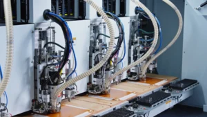
Advanced laminating techniques form the heart of Rigid-Flex PCB manufacturing. Unlike conventional rigid PCB lamination, which simply applies heat and pressure to cure prepreg materials, Rigid-Flex lamination must carefully control pressure distribution to avoid damaging flexible sections while ensuring adequate bonding in rigid areas. Vacuum lamination systems have become standard for high-reliability applications, removing trapped air that could create voids and subsequent delamination failures.
The challenge intensifies with adhesiveless constructions. These materials often require higher temperatures and precisely controlled pressure profiles to achieve proper bonding without causing flow issues that could create wrinkles or dimensional distortion in flex areas. At Flex Plus, we’ve invested in advanced lamination presses with multiple heating zones and programmable pressure sequences, allowing our technicians to optimize cycles for specific material combinations. This level of control isn’t just about quality—it’s about consistently achieving the material properties that engineers designed for.
Drilling and routing operations require equal precision. Flexible materials tend to deform under mechanical stress, making conventional drilling challenging. Laser drilling has largely replaced mechanical drilling for small vias in flex areas, providing clean holes without inducing stress in surrounding materials. Similarly, laser routing often replaces mechanical routing for flex circuit outlines, eliminating the deformation that can occur when blades drag through flexible substrates.
Copper plating in Rigid-Flex boards presents unique challenges. The flex areas require uniform plating thickness while avoiding excessive copper buildup that would stiffen the circuit and reduce its fatigue life. Advanced plating chemistries and careful control of current density ensure that copper deposits evenly across complex three-dimensional geometries, maintaining the electrical and mechanical properties the design requires.
Perhaps most critical is the testing regime. Because Rigid-Flex PCBs often serve in critical applications—medical life support equipment, aerospace flight controls, electric vehicle safety systems—comprehensive testing isn’t optional. This includes not just electrical testing to verify connectivity and impedance, but also mechanical testing that simulates the flexing cycles the board will experience in service. Automated optical inspection (AOI) catches manufacturing defects before assembly, while cross-sectional analysis of sample boards verifies that lamination achieved proper adhesion and that no delamination exists at critical interfaces.
The manufacturing precision required for Rigid-Flex PCBs explains why working with experienced manufacturers matters so profoundly. Companies like Flex Plus, with over two decades of specialized experience and ISO 9001, ISO 13485, and IATF 16949 certifications, have developed the process control and quality systems necessary to consistently deliver boards that meet or exceed design specifications. This isn’t about marketing—it’s about the accumulated knowledge of hundreds of thousands of boards produced, each one teaching lessons about what works and what fails.
Real-World Applications: Where Material Choices Prove Their Worth
The true test of any technology lies not in specifications but in real-world performance. Rigid-Flex PCBs have proven their value across an impressive range of demanding applications, with material choices often determining success or failure.
In aerospace applications, Rigid-Flex PCBs face perhaps the most extreme operating conditions imaginable. Aircraft electronics must function reliably across temperature ranges from -55°C at altitude to 125°C in equipment bays, while withstanding vibration, shock, and potentially corrosive atmospheres. The emerging low-altitude airspace sector—including drones, eVTOL vehicles, and air taxis—presents similar challenges with even tighter weight constraints. Here, the choice of high-temperature adhesiveless laminates and carefully selected rigid section materials directly impacts mission success. A battery management system that fails due to thermal degradation doesn’t just ground an aircraft—it potentially threatens lives.
Medical devices present different but equally stringent requirements. Consider implantable cardiac monitors or neural interface devices—Rigid-Flex PCBs in these applications must remain reliable for years or even decades while subjected to the corrosive environment of bodily fluids at 37°C. Material biocompatibility becomes paramount, requiring ISO 13485-certified manufacturing and materials that resist degradation in physiological conditions. The flexible sections enable these devices to conform to anatomical structures, reducing patient discomfort while the rigid sections support sensitive analog circuitry. Material choices here aren’t just about performance—they’re about patient safety and regulatory compliance.
Electric vehicles showcase Rigid-Flex PCBs across multiple subsystems. Battery management systems, head-up displays, advanced driver assistance systems (ADAS), and camera modules all benefit from the space savings and reliability improvements these boards provide. Under-hood temperatures can exceed 125°C, while passenger compartment electronics face rapid thermal cycling as vehicles heat in sunlight then cool overnight. The material durability and thermal performance become direct factors in warranty costs—a failed display controller at 60,000 miles represents not just a replacement expense but potential brand damage.
Consumer electronics, particularly smartphones and wearable devices, push Rigid-Flex PCBs toward extreme miniaturization. These boards might fold multiple times to fit within device volumes measured in cubic centimeters, with overall thickness sometimes reaching as thin as 25 microns with gold plating on double-sided designs. Here, the ultra-thin polyimide substrates and precision copper foils determine whether the device survives drop tests and years of user handling. The material choices directly impact product returns and customer satisfaction scores.
Industrial control systems represent another critical application domain. Robotic arms, automated assembly equipment, and process control systems operate continuously in environments that might include temperature extremes, chemical exposure, and constant vibration. Rigid-Flex PCBs in these applications must deliver decades of maintenance-free operation—material degradation translates directly to production downtime costing thousands of dollars per hour. The long-term stability of laminate materials and copper traces becomes an economic factor, not just an engineering consideration.
The Path Forward: Innovation Through Material Science
As we look toward the future, the relationship between material choice and Rigid-Flex PCB lifespan continues to evolve. Emerging materials promise even better performance, while new applications demand capabilities beyond what current technologies can deliver.
Liquid crystal polymer (LCP) substrates are gaining traction for high-frequency applications, offering lower dielectric constants and better moisture resistance than polyimide, though at significantly higher cost. For telecommunications equipment operating in millimeter-wave frequencies, these materials extend useful bandwidth while maintaining signal integrity over the product’s lifetime.
Stretchable circuit materials, including TPU (thermoplastic polyurethane) substrates, open entirely new application domains. Unlike traditional flex circuits that bend but don’t stretch, these materials accommodate elastic deformation—critical for wearable medical sensors, soft robotics, and conformable electronics that must move with the human body. Flex Plus has pioneered biocompatible TPU circuits ranging from 10-600mm with copper foils from 18-70μm, enabling medical applications previously impossible with conventional materials.
Advanced thermal management materials address one of the most significant limitations of current Rigid-Flex designs. Innovative solutions like flexible heat dissipation flow channels integrate thermal management directly into the circuit structure, enabling higher power densities while maintaining reliability. As electric vehicle power electronics and 5G telecommunications infrastructure push toward higher power levels, these thermal innovations become critical for product longevity.
The manufacturing processes themselves continue advancing. Additive manufacturing techniques, including printed electronics and selective metallization, promise to complement traditional subtractive processes. While not yet replacing conventional manufacturing for most applications, these technologies enable rapid prototyping and specialized low-volume production, accelerating the development cycle for innovative products.
Conclusion: Excellence Through Informed Choices
The journey from Rigid-Flex PCB concept to reliable product spans countless decisions, but few prove as consequential as material selection. Every substrate, every copper foil, every laminating adhesive or adhesiveless construction carries implications that echo through years of product operation. The difference between a circuit that delights customers for a decade and one that disappoints within months often traces back to choices made during initial specification.
At Flex Plus (Xiamen) Co., Ltd, our philosophy centers on partnership with customers to make these critical decisions wisely. With over 20 years of manufacturing experience, comprehensive certifications including ISO 9001, ISO 13485, and IATF 16949, and advanced capabilities spanning from ultra-thin 25-micron designs to complex rigid-flex constructions, we’ve learned that excellence in Rigid-Flex PCBs comes not from compromising but from understanding—understanding how materials behave under stress, how designs interact with manufacturing realities, and how today’s choices determine tomorrow’s reliability.
Whether you’re developing next-generation electric vehicle systems, revolutionary medical devices, or breakthrough consumer electronics, the materials forming your Rigid-Flex PCBs deserve careful consideration. They represent the foundation upon which your innovation stands or falls. As industries push toward smaller, lighter, more reliable electronics operating in increasingly demanding environments, the role of material science in determining product lifespan only grows more critical.
The question isn’t whether material choice matters—experience has settled that debate definitively. The question is whether you have the partnership, expertise, and manufacturing capability to translate material specifications into lasting reliability. That’s where two decades of focused experience, comprehensive engineering support, and certified manufacturing excellence make the difference between theory and reality, between prototypes and proven products, between good enough and genuinely excellent.